Course compass
Guiding question: Why is an injector not simply “a plate with holes”?
Markers: 📏 MEASURED · 📐 CONVENTION · 🧮 CALCULATED · 🎓 TEACHING ASSUMPTION · ⚠️ APPROXIMATION
- understand injector function
- distinguish global and local
- connect mixing and stability
- reason without manufacturing geometry
Key idea
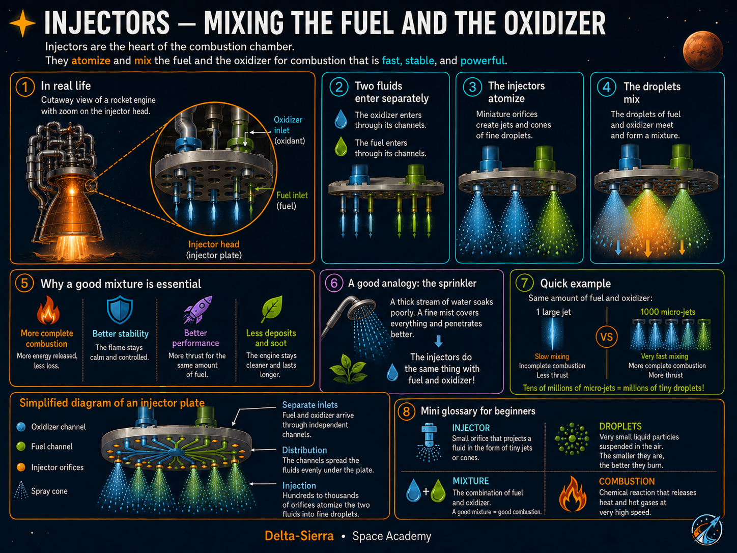
Injectors: turn two feed streams into a mixture that can burn stably. The question to solve is: Why is an injector not simply “a plate with holes”? Markers: 📏 MEASURED · 📐 CONVENTION · 🧮 CALCULATED · 🎓 TEACHING ASSUMPTION · ⚠️ APPROXIMATION understand injector function distinguish global and local connect mixing and stability reason without manufacturing geometry? The injector distributes propellants into the chamber and creates jets, films, or patterns that promote atomization and mixing depending on architecture. The rest of the course turns that idea into an auditable line of reasoning: explicit units, stated assumptions, reproducible calculations, order-of-magnitude checks and interpretation limits. A result is useful only when the reader can explain what it measures, where every input came from and which engineering decision it can support.
Starting synthesis: derivations, examples, limitations and sources are developed in the course body.
Key concepts before you begin
propellant · thrust · mass flow rate · cavitation · unit
1 — Distribute and mix

The injector distributes propellants into the chamber and creates jets, films, or patterns that promote atomization and mixing depending on architecture.
Mixing quality affects where and how energy is released.
2 — Average is not enough
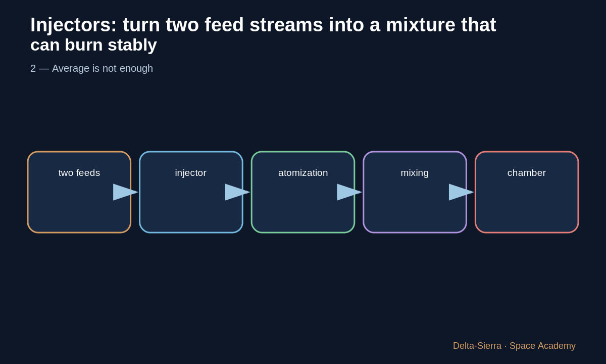
The correct global flow ratio does not guarantee that every chamber region receives the same local mixture.
Non-uniformity can produce hot spots or undesirable combustion dynamics.
3 — Injector interacts with combustion
NASA documented on the F-1 how injector geometry and baffles played a crucial role in suppressing combustion instability.
A seemingly static component participates in full-engine dynamics.
4 — Cooling and walls
Some architectures also use film or near-wall distribution strategies. The choice is part of thermal and combustion trade-offs.
This lesson provides no orifice geometry or manufacturing recipe; it teaches system function.
Three complete examples: change one assumption to understand
Before each calculation, identify where every number comes from and whether it is measured, conventional, assumed, or calculated.
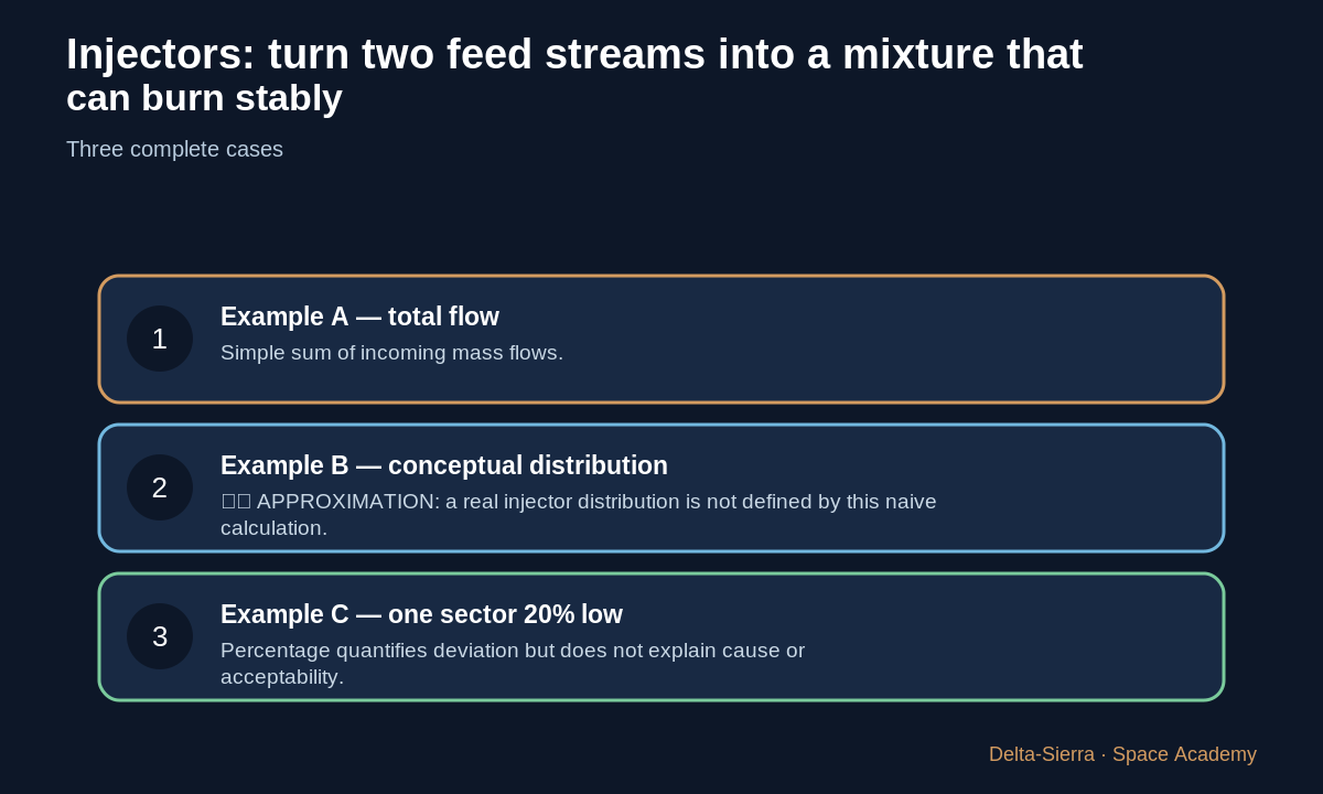
Example A — total flow
Oxidizer 30 kg/s + fuel 10 kg/s = 40 kg/s total.
Simple sum of incoming mass flows.
Example B — conceptual distribution
If 40 kg/s were ideally divided across 4 equal conceptual sectors, average=10 kg/s/sector.
⚠️ APPROXIMATION: a real injector distribution is not defined by this naive calculation.
Example C — one sector 20% low
Average 10, measured sector 8: difference=(8−10)/10=−20%.
Percentage quantifies deviation but does not explain cause or acceptability.
Inverse calculation
If four conceptual sectors must total 40 and three are 10, the fourth must also be 10 to satisfy the sum. This arithmetic check does not prove good combustion.
Common trap and result check
Trap: believing a correct global mixture ratio automatically guarantees local uniformity and stability.
In a real engine system, a conceptual result must later be checked against fluid properties, margins, tests, and qualification.
Exercises and answers
Function
Explain the function of each block without jargon.
Sensitivity
Halve one assumption and predict the consequence.
Limit
Name one reason the teaching model is insufficient for a real engine.