


MARS BIBLE — REFERENCE DOSSIER
Spacecraft structures, mechanisms and integration for Mars: survive loads, deploy and remain compatible
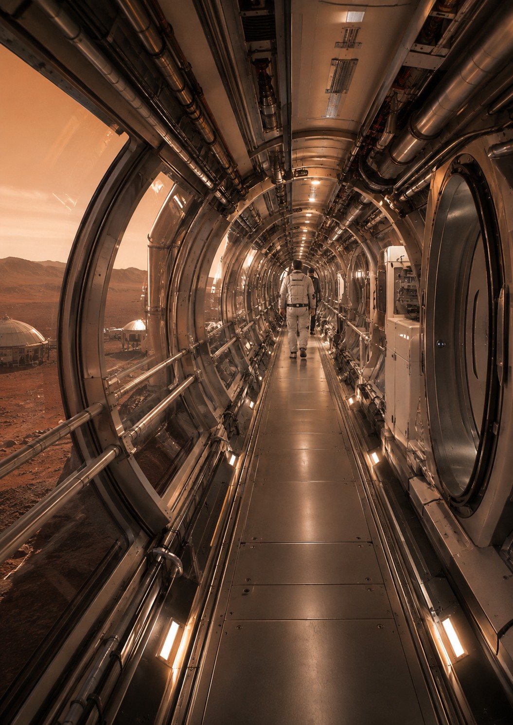
Load paths, stiffness, vibration, fatigue, buckling, fasteners, mechanisms, tribology, deployments, interfaces and integrated qualification.
Why structures and mechanisms are system interfaces
Structures and mechanisms: loads, interfaces and service life
1. Structure is both skeleton and reference geometry
Structure carries hardware and transfers loads to the launcher or engines, while maintaining the geometry needed by pointing, mechanisms, seals and plumbing. Its job is not merely to avoid breaking. Excess flexibility can disturb antenna pointing, engine alignment or clearances. Strength, stiffness, stability and mass are related but distinct objectives.
2. Load paths: follow force to its reaction
During launch, equipment creates inertial force from its mass and acceleration. That force passes through fasteners, panels, frames and the adapter, so a small component can become critical. Engineers trace load paths and check each interface. A strong panel cannot rescue a weak insert. The same reasoning applies to internal pressure, engine loads, docking and handling.
3. Stiffness and natural frequencies
Every structure has natural vibration modes. Excitation near a natural frequency can amplify response. Modal models predict those frequencies and tests measure them. Mass distribution strongly affects the result, so moving a battery or adding a tank can change global vibration behaviour even when structural parts themselves are unchanged.
4. Buckling: lose stability before material failure
A thin compressed shell can suddenly deform while material stress remains below a simple failure limit. This is buckling. Tanks, panels and lightweight structures therefore need stability analysis with realistic imperfections and boundary conditions. Stronger material alone may not solve the problem; geometry, stiffeners and attachment can matter more.
5. Fatigue and thermomechanical cycling
Repeated loads can initiate cracks. Vibration, pressure cycles, hot-cold cycles and mechanism motion accumulate damage. Mars missions add duration and repetition. Stress concentrations around holes and welds require attention. Inspection and non-destructive evaluation may be needed for reused or repaired hardware, so a settlement must learn not only to manufacture but to judge continued structural fitness.
6. Fasteners: small parts, large consequences
Bolts, inserts, rivets, adhesives and interfaces transfer loads and can loosen, crack or slip. Preload, friction and thermal environment matter. An inaccessible fastener can also become a maintenance problem. Standardising some sizes and tools reduces spare-part diversity, turning ordinary fasteners into an industrial advantage for Mars.
7. Mechanisms: adding motion adds risk
Arrays, antennas, latches, arms, valves and covers use mechanisms. NASA notes that mechanisms add capability and complexity and can create single-point-failure risk. A one-time deployment cannot rely on thousands of flight cycles for confidence. Simplicity, margin, tribology control and representative testing matter, and architecture should ask whether motion can be removed or made non-critical.
8. Tribology: friction, wear, lubrication, vacuum and dust
Moving surfaces need controlled friction. Vacuum can make some lubricants unsuitable; temperature changes viscosity and clearance; Mars dust can be abrasive. Material pairs, coatings and lubricants are chosen for the environment. Surface mechanisms also need planned cleaning and wear-part replacement rather than improvised maintenance.
9. Clearance and thermal expansion: a mechanism can jam without breaking. Different materials expand differently. A clearance that is correct at room temperature can become too small when cold or too large when hot. Manufacturing tolerances add to thermal variation. Analysis therefore covers minimum and maximum clearance cases, and actuators need enough torque for the worst case without damaging the mechanism in the easiest case.
10. Sensors and state confirmation
A critical mechanism should not be declared deployed merely because a command was sent. Limit switches, encoders, motor current, cable tension or imagery provide different evidence. Combining clues helps distinguish sensor failure from incomplete motion. On Mars, that information may determine whether a crew needs an EVA repair, so observability must be designed into the mechanism.
11. Integration: two correct subsystems can be incompatible
Structure defines holes, volumes and stiffness; power adds cables and connectors; thermal control needs conductive interfaces; avionics adds networks; propulsion adds plumbing and plume zones. Integration turns these constraints into a real configuration. Local changes require impact analysis, and interface documents, 3D models, wiring data and configuration control maintain a shared technical truth.
12. Integrated testing: reproduce real interactions where possible. Separate tests are not enough. Vibration can affect connectors; thermal vacuum can change mechanism resistance; a radio can disturb a sensor; software can command hardware in a bad sequence. Integrated tests look for these interactions. The whole mission cannot be reproduced, so teams must know what was tested together, what was simulated and what remains extrapolated.
13. Repair, reproduce, requalify: the Mars challenge. On Mars, replacing a hinge or printing a part is not enough. Material, dimensions, treatment, lubrication, tolerance and load behaviour must be checked. A repair can alter structural models or fatigue risk. The settlement will need measurement, testing, non-destructive inspection and acceptance procedures. Mechanical autonomy begins when locally made parts can be judged truly fit for service.
14. Habitat pressurisation: structure works continuously
A pressurised crew volume continuously loads its walls and openings. Windows, airlocks, seals and penetrations become critical structural details, and pressure cycling adds fatigue. Local repair must restore both leak tightness and load-carrying capability, so habitat qualification cannot be reduced to a simple leak test.
15. Micrometeoroids and local damage
An impact can damage a wall, radiator, cable or line without immediately destroying the whole vehicle. Architecture combines protection, separation, leak detection and isolation. Rapid damage localisation and access directly affect survivability in interplanetary vehicles and Mars habitats, again linking structure to maintenance.
16. Mars assembly: tolerance stack-up
Local manufacturing creates dimensional variation. If each part sits at one tolerance extreme, the final assembly may no longer fit. Tolerance-stack analysis predicts those effects. Adjustable interfaces, shims or locally machined surfaces can absorb variation, which becomes essential when a settlement assembles large vehicles from parts made by different machines and material batches.
17. EVA mechanisms: design for gloves and dust
A handle, latch or fastener easy to use bare-handed can be difficult in a spacesuit. Forces, dimensions, visual cues and tactile feedback must account for gloves and field of view. Dust can hide indicators or contaminate connectors. External maintenance should therefore be tested under representative conditions, not only described on paper.
18. Standardise without freezing evolution
Common mechanical interfaces make modules, arms, tools and payloads interchangeable, but freezing a poor standard too early creates technical debt. One strategy is to stabilise critical envelopes and interfaces while allowing internal components to evolve, with adapters bridging generations. On Mars, standards governance becomes an industrial issue as important as individual part performance.
Critical interfaces and system consequences that are easy to miss
Structure: loads, vibration, stiffness and margins
Space structure is more than static weight
Spacecraft experience acceleration, vibration, acoustic, pressure, manoeuvre and thermal loads. During launch, even a light box can create large forces because acceleration multiplies inertia. Loads travel through equipment, fasteners, panels, frames and the launch adapter. A small insert or bolt may therefore control a much larger assembly. Start by identifying load paths, not by simply making panels thicker.
Strength, stiffness and stability are different
A part can remain unbroken yet become unusable. Excess deformation can spoil antenna pointing or jam a mechanism. Stiffness controls deformation and natural frequencies; stability includes buckling, where a compressed shell may suddenly deform before the material reaches a simple strength limit. Margins must therefore be assessed for each relevant failure mode.
Why launch vibration matters
Launch vibration and acoustics excite structural natural frequencies. Excitation near a mode can amplify response through resonance. Modal models and tests are used to check real frequencies and damping. Even a modest mass change can move a natural frequency, so mechanical configuration must stay controlled through integration.
Fatigue makes repeated small loads important
Failure can grow from repeated cycles rather than one extreme load. Thermal cycles, pressure cycles, mechanisms and vibration can initiate and propagate cracks. Long Mars missions increase some cycle counts, making stress concentrations, manufacturing quality and inspection important.
Thermal expansion becomes structural
Different materials expand differently. Rigidly joining aluminium, composites, optics and electronics can create thermal stress or misalignment. Flexible mounts, controlled clearances or compatible materials are therefore used. Structural analysis and thermal analysis cannot be isolated from each other.
A positive margin is not automatic safety
Every margin depends on assumptions about loads, material properties, factors, geometry, temperature and manufacturing scatter. A large numerical margin is meaningless if the load case is wrong. Data provenance and combined worst cases matter.
Test and model correlation
Finite-element analysis remains a model. Vibration tests, static tests, modal measurements and inspection compare reality with prediction. Differences are used to update the model before extrapolation. This analysis-test-correlation loop turns a theoretical model into a trusted engineering tool.
Mechanisms: deployments, actuators and reliability
A mechanism turns command into physical motion
Motors, gears, springs, hinges, latches, cables, bearings and sensors can form a spacecraft mechanism. It must work after launch vibration, vacuum, extreme temperature and sometimes months of storage. One-shot deployments gain confidence from simplicity, margins, material control and representative testing rather than in-flight statistics.
Tribology changes in vacuum and dust
Moving surfaces depend on friction, wear and lubrication. Vacuum can make terrestrial lubricants unsuitable, while Mars dust adds abrasion and contamination. Material pairs, coatings, compatible lubricants, clearances, cleaning and inspection therefore matter.
Clearance, thermal expansion and resisting torque
A joint that moves at room temperature can bind when cold or become loose when hot. Analysis covers manufacturing tolerances, temperature, wear and alignment. Actuators need enough torque margin without damaging hardware at stops.
Deployment can be irreversible
A solar-array or antenna deployment may happen only once. Designers must plan for false sensors, motor overcurrent and partial deployment, and recovery logic is part of the mechanism system, not merely software.
Multiple position clues improve diagnosis
Limit switches, encoders, motor current and cameras each provide different evidence. Each can be ambiguous on its own, so combining them improves diagnosis, especially when a Mars crew must decide whether physical intervention is safe.
Mechanisms can create single-point failures
NASA notes that mechanisms add capability and complexity and can introduce single-point-failure risk. System design should ask whether a minimum mission is possible without the mechanism, whether independent paths exist or whether a fixed architecture can eliminate motion entirely.
Repairability on Mars
Surface equipment may be repairable, increasing the value of accessible fasteners, standard parts, lifting tools and documentation. EVA dexterity and contamination still constrain what can be done outside, so repair tasks should be allocated between external work and pressurised workshops.
Integration: interfaces, budgets, verification and validation
Integration means managing boundaries
Two units can work separately and fail when connected. Integration verifies mechanical, electrical, thermal, software, RF, fluid and operational interfaces. Interface Control Documents formalise parameters and ownership, but their value depends on remaining current as the design changes.
Budgets evolve until late in the project
Mass, peak power, data rate and thermal predictions change as detail grows. Systems engineering tracks budgets and margins over time and defines when changes require approval and re-analysis by affected subsystems.
Verification and validation are different
Verification asks whether the system meets its requirements. Validation asks whether those requirements and the resulting system actually satisfy the mission need. Both are necessary; a perfectly compliant system can still solve the wrong problem.
Test as you fly, fly as you test
Testing should represent flight configuration and sequences as closely as practical, while flight should avoid untested modes. A complete Mars mission cannot be reproduced on Earth, so environmental tests, simulations, hardware benches and operational rehearsals are combined with explicit knowledge of what remains extrapolated.
Electromagnetic compatibility is invisible but real
Power converters, motors, radios and digital clocks can disturb other equipment through conducted or radiated noise. Cable routing, shielding, grounding and filters are integration issues, and some problems appear only in the complete configuration.
Anomaly management requires cause, not just replacement
Test anomalies must be recorded, reproduced where possible, analysed and closed with rationale. Replacing a failed part without understanding the cause can hide a systemic problem. Traceability lets similar hardware and interfaces be checked.
Mars integration becomes logistics infrastructure
Adding a module to a settlement requires compatibility with existing power, data, fluids, dimensions, software, safety and maintenance. Local interface standards, test benches, calibration references and configuration management become part of industrial autonomy.
Engineering deep dive — connect pressure, stiffness, mechanisms and interfaces to real service life
A pressure structure works continuously even when the vehicle appears idle. A cylindrical habitat under internal pressure carries membrane stress. In a simplified thin-wall model, circumferential stress is approximately σ = p r / t, where p is pressure difference, r radius and t wall thickness. With p = 70 kPa, r = 2.5 m and t = 5 mm, the result is about 35 MPa. This is not a design thickness: it ignores openings, joints, stress concentrations, safety factors, local buckling and fatigue. It simply shows that cabin pressure is a continuous structural load.
Every window, hatch, cable penetration and attachment interrupts ideal geometry and concentrates load. Reinforcement restores strength but adds mass and local stiffness. Real structure is therefore a network of load paths. The recurring question is where force enters, how it travels and where it is reacted.
Mars pressure cycles may be fewer than aircraft cycles but continue for decades. Repairs, impacts, local corrosion and interior modifications change the history. Structural records should therefore track events like a fatigue log.
Stiffness and natural frequencies can govern integration as strongly as strength. A structure can be strong enough not to break and still be too flexible for the rest of the system. Solar arrays, antennas, optics and mechanisms need a stable base. Launch vibration can excite natural modes and amplify motion. Design therefore includes frequency margins and modal analysis.
The issue continues after launch. A large vehicle assembled in space changes modes as modules are attached and tanks empty. Robotic arms, centrifuges and rotating mechanisms add excitation. Attitude control must understand structural flexibility to avoid control-structure interaction.
Integrated tests validate these models. A subsystem tested alone on a rigid fixture can behave differently on a flexible spacecraft. Verification should progressively approach real configuration.
Buckling reminds us that geometry can fail before material strength is exhausted. A thin panel or member in compression can lose stability and deform suddenly while material stress remains below ultimate strength. Lightweight space structures are especially sensitive. Small imperfections, cut-outs, joints and eccentric load often reduce performance relative to an ideal model.
Design therefore uses imperfection factors, nonlinear analysis and test. A local repair can change panel stability well beyond the patch. On Mars, reproducing a part to the same dimensions does not guarantee the same performance if material or process is different.
This directly links local manufacturing and qualification. Secondary parts may be replaced after modest inspection; primary pressure structure demands a much stronger evidence chain. The settlement will need explicit boundaries around what it can requalify locally.
Mechanisms add hidden states that software must understand. An antenna, hatch or panel is not simply open or closed. It has intermediate positions, clearances, loads, latches and sensors. A motor can turn without reaching the stop; a sensor can say “closed” while a mechanical latch is not engaged. Critical functions therefore need state confirmation from more than one cue where practical.
Vacuum, dust and temperature affect tribology. Lubricants behave differently, surfaces wear and clearances evolve. Exterior Martian mechanisms need cleaning, inspection and replaceability. An inaccessible moving part becomes a life-limited component.
Degraded operation matters too. Can a hatch be closed manually? Can a radiator be deployed using backup actuation? Can an EVA crew release a latch with gloves? Mechanical recovery deserves the same design attention as nominal automation.
The interface is often where two good subsystems become a bad vehicle. A module may satisfy its mass requirement and a launcher its payload requirement while integration still fails through centre of gravity, load path or geometry. Integration therefore manages budgets: mass, power, data, thermal, volume, frequency and structural loads. Subsystems should provide tolerances as well as nominal values.
Margins must not be spent twice. If each team assumes “the system” can absorb its ten-percent growth, the final vehicle can discover the same reserve has been promised several times. Central, version-controlled budgets make margin consumption visible.
Over decades, standardized interfaces support evolution. New modules and vehicles can connect without redesigning the whole base. Yet geometric compatibility is not enough: power, data and safety rules must also match. Interoperability is a complete engineering contract.
Treating structure as geometry of loads, interfaces and tests
Connect internal pressure, radius and wall thickness. A first approximation for a thin cylindrical pressure shell gives hoop stress σ ≈ pr/t. Here σ is mechanical stress, p is pressure difference, r is radius and t is resisting thickness. With p = 70 kPa, r = 2. kPa means kilopascal and MPa megapascal. This is not final sizing: openings, joints, buckling, launch loads, fatigue, stress concentrations and safety factors matter. It does provide an order of magnitude and shows directly why larger pressurized radius increases structural demand.
A lightweight structure is therefore not simply less material. It places material along load paths and prevents local interfaces from erasing gains made elsewhere. Hatches, windows, mechanisms and attachments can dominate over an idealized shell.
Design mechanisms for dormancy and contamination. A mechanism may remain unused for months and then have to work correctly on its first attempt. Hinges, latches, antennas, arrays, hatches and docking hardware face limited lubrication, thermal cycling, radiation and sometimes dust. Reliability must cover not only cycle count but dormancy, contamination and tolerance change after ageing.
For one-shot functions, testing should reproduce the actual chain as far as practical: power, software, sensors, sequence and load. Testing an actuator alone does not prove that the integrated mechanism will deploy when structural distortion, connectors and command logic interact.
Make integration a discipline of coupled budgets. Every subsystem consumes several budgets at once: mass, volume, power, thermal rejection, data, vibration, field of view, access and integration time. A change that saves 20 kg but adds radiator area, shifts center of gravity or blocks a hatch may be negative at vehicle level. Margins therefore have to be managed together rather than independently by each team.
This is why current mass and configuration models matter. A Mars vehicle evolves over years; a forgotten interface discovered late can cost more than an ambitious technology. Good integration is not the production of more documents but the ability to expose the consequences of a change immediately.
Verification cases and operational margin
Validate interfaces with end-to-end tests. Integration failures often appear at boundaries between subsystems that passed separate tests. A mechanism may work on its bench but fail when the structure deflects; an antenna may deploy into a sensor field of view; equipment may meet its mass allocation while making maintenance access impossible. End-to-end tests therefore need realistic geometry, harnesses, software, loads and access methods.
Digital models catch many conflicts but do not replace all physical verification. Tolerances, cable flexibility, friction, connector behavior and human sequences remain difficult to represent perfectly. Integration planning should state what is proven by analysis, simulation, inspection or test and preserve traceability to that evidence.
For pressurized elements, verification must also follow structural life after launch. Launch loads, pressure cycles, mechanism shocks and thermal changes can introduce damage that was absent during final ground inspection. Inspections, sensors or leak tests after major events can confirm that analytical margin still exists. Structure is therefore not certified once and forgotten; it is a system whose condition has to remain known.
Make the structure inspectable, repairable, and compatible with the whole mission
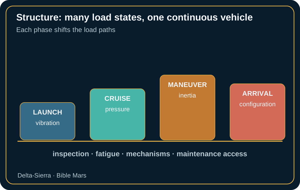
One structure must survive several mechanical worlds
The same vehicle sees very different environments. Launch is dominated by dynamic, acoustic, and vibration loads. During cruise, internal pressure, thermal gradients, mechanism cycles, and aging become more important. At arrival, maneuvers, capture, or a different configuration can shift load paths again. Credible design therefore cannot be reduced to one maximum stress; it links each mission phase to load combinations and failure modes.
NASA structural standards, including NASA-STD-5001B and associated load-analysis documents, provide frameworks for factors, verification, and analysis. They do not define a universal Mars pressure shell. Their value is methodological: identify load cases, uncertainties, factors, qualification methods, and evidence that hardware preserves its function. Configuration changes also have to be checked so that a late change does not create a load case more severe than the one originally verified.
Cabin pressure provides a simple example. For a thin cylinder, hoop stress is approximately σ = p r / t, where σ is stress, p is pressure difference, r is radius, and t is wall thickness. With p = 70 kPa, r = 2.5 m, and t = 8 mm, the result is about 21.9 MPa before local concentrations, joints, openings, and safety factors. The important lesson is scaling: doubling radius doubles this membrane stress if everything else remains unchanged. A larger habitat is not a simple geometric enlargement.
Openings and interfaces are often harder than large surfaces
A uniform shell is comparatively straightforward to model. Difficulty concentrates around windows, cable penetrations, fluid lines, hatches, radiator supports, antennas, tanks, and docking points. Every opening redirects load and creates interfaces among materials, fasteners, and seals. Integration therefore has to treat local details as seriously as the overall structural form.
Mechanism interfaces are particularly sensitive. A deployable panel can have excellent strength margins and still fail because a hinge binds, a tolerance changes with temperature, or a cable interferes with motion. Mechanisms need geometric margin, state sensing, repeatability, and sometimes a manual or alternative actuation path. A system that only works during one pristine first deployment is weak for a long-duration mission.
The structure also has to preserve maintenance access. A stiffener placed in front of a filter, a harness trapped behind a bulkhead, or an inaccessible fastener can make replacement of a critical item impossible. The mass of a removable panel must then be compared with the cost of an unrecoverable failure. Accessibility is part of mechanical integration.
Fatigue, damage, and nondestructive evaluation become operational topics
On a long or reusable mission, the question is no longer only whether the part survives launch, but how its strength evolves after thousands of cycles, thermal gradients, and possible impacts. Damage can remain microscopic before becoming critical. Design should identify locations where cracking is credible and select inspection methods that can actually be used.
Nondestructive evaluation may use visual inspection, ultrasound, eddy current, or other methods depending on material and geometry. A terrestrial technique is useful on Mars only if the instrument, calibration, access, skill, and interpretation are available. Architecture should avoid creating critical areas that no onboard method can inspect. A crack is not operationally detectable if the probe cannot reach the surface.
Trend monitoring provides another form of evidence. Periodic measurement of a natural frequency, mechanism free play, or deflection under a known load can reveal change before failure. If a structural frequency falls from 12.0 to 11.4 Hz in the same configuration, the roughly 5% change deserves investigation: stiffness loss, a loose attachment, shifted mass, or measurement difference. The number is not a diagnosis by itself; it is a health signal.
Structural modes must remain compatible with equipment and control
A flexible structure interacts with guidance, arrays, antennas, and mechanisms. If an actuator excites a natural mode close to its control frequency, the vehicle can vibrate even though every component is individually nominal. Dynamic integration therefore connects stiffness, mass distribution, modal frequencies, and control laws.
For a simple mass-spring model, natural frequency is f = (1 / 2π) √(k/m), where k is stiffness and m is mass. If mass grows by 21% with no stiffness change, frequency is multiplied by 1/√1.21 ≈ 0.91. A 10% dynamic separation margin can almost disappear. That simple relation explains why a late mass change must feed back into dynamic analysis.
Modal testing and flight measurements can update the model. The objective is not a perfect model but confidence that the real vehicle remains inside the envelope in which control laws and mechanisms were verified. A reusable architecture should preserve this model–measurement–correction loop through its life.
Prepare repair without turning the structure into a permanent workshop
Not every structural repair will be possible. Strategy should distinguish tolerable damage, temporary repair, permanent repair, and acceptable loss of function. A local repair may use a patch, adhesive, mechanical fastener, or fabricated part, but it still needs an understandable load path and a verification method. Adding material without knowing where loads flow can move the problem rather than solve it.
A credible scenario is a secondary support that cracks after many cycles. The first action is to unload the function if possible, then characterize crack extent and boundary conditions. Repair is sized for the load actually required until the next intervention opportunity, rather than blindly reproducing the original part. Inspection and a functional test close the loop, and configuration records capture the new limitation.
This philosophy encourages some areas to be designed as repair interfaces: access, clean surfaces, redundant attachment, measurement, and documentation. The Mars spacecraft structure then becomes more than the skeleton that survives launch. It becomes a system whose condition can be understood and, within defined limits, restored far from Earth.
Mechanical case study: a mechanism stops halfway through deployment
After several months of cruise, a radiator needs a new configuration for a warmer mission phase. Deployment begins and stops at 62% of travel. Motor current is higher than expected, but no impact is detected. The worst response would be to repeat the full-power command immediately without understanding the resistance; a simple friction problem can become a broken gear or distorted structure.
Avionics first confirms position through several forms of evidence: angle sensor, motor current, possible imagery, and thermal response. Structures provides allowable loads for the intermediate position. Thermal control calculates how long that geometry can be tolerated. The event becomes an integrated problem of time available, mechanical force, and heat-rejection performance.
Suppose nominal motor torque is 18 N·m and protection trips at 27 N·m. A manual or low-speed attempt should not automatically drive to 27 N·m. A cautious procedure might permit controlled rise to 22 N·m while monitoring motion and current, then stop if no displacement occurs. N·m means newton-meter, the unit of torque. The numerical limit is illustrative; the real value must come from mechanism design and qualification evidence.
If the radiator can operate at 62% for twelve hours, the crew gains an inspection window. Vehicle attitude may be adjusted to lower thermal demand, a mechanism zone inspected, a cable checked, or a bearing locally warmed if the design permits it. Multiple sensing paths and a stable intermediate position turn a deployment anomaly into a potentially recoverable problem.
After recovery, the mission still has to decide whether normal use is safe. Motion achieved at abnormal torque may have produced hidden damage. Future cycles can be limited, monitoring increased, or the recovered configuration retained if it remains compatible with the rest of the flight. Configuration records should capture the restriction.
The case shows why structures and mechanisms are not only launch disciplines. During the journey they become operational systems whose limits must be known, observable, and convertible into mission options.
A Mars spacecraft structure is a load path, not an abstract shell
The vehicle must survive launch, maneuvers, vibration, cabin pressure, thermal cycling and local loads at every interface. Cruise is not necessarily the structural sizing case: a few minutes of launch can impose far larger acceleration and vibration. The same structure must then retain alignment and stiffness for months while propellant and consumable masses change.
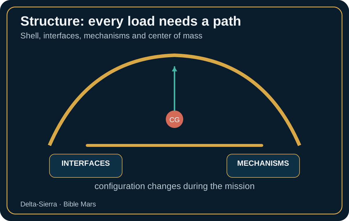
A structural model describes how load reaches the elements that carry it. Antennas, radiators and solar arrays transmit inertia and vibration through attachments and panels. Too little stiffness can disturb pointing; excessive local stiffness can concentrate stress. Mechanical integration therefore trades strength, stiffness, mass and dynamic response.
Why natural frequency matters
A simple mass-spring system has natural frequency f = (1/2π)√(k/m), where k is stiffness in newtons per metre and m is mass in kilograms. Increasing attached mass without increasing stiffness lowers natural frequency. This explains why a late heavy component can move a structural mode toward launch excitation. π is pi and √ denotes square root. Real spacecraft have many coupled modes, but the simple relation preserves the engineering intuition.
Vibration testing and finite-element models are used together. Large differences between measured and predicted modes should trigger model correction, not merely an arbitrary increase in structural margin.
Mechanisms turn a rigid structure into a configurable vehicle
Solar arrays, antennas, hatches, valves, joints and docking hardware introduce moving states, sensors, actuators and possible jams. A one-time deployment has different reliability needs from a mechanism cycled thousands of times. Wear, lubrication, contamination and testability become long-duration concerns.
Design should ask what happens after partial deployment. Can the vehicle survive with one solar wing unavailable? Can power be reduced if a radiator does not latch? Is low-rate communication possible if the high-gain antenna cannot point? Structural and mechanism faults therefore connect directly to power, thermal and communications architecture.
Integration must preserve access to hardware that may need repair
Compact spacecraft naturally fill every volume. That can leave pumps, electronics or connectors inaccessible without removing healthy equipment. For a distant mission, access is an architectural property. Repair time, energy isolation, tool clearance and component movement should be tested in physical or digital mockups.
NASA workmanship and parts-assurance standards remind engineers that interfaces depend on ordinary details: crimps, fasteners, connectors, inspection and storage. On Mars, those details matter more because replacements cannot arrive within hours. Assembly records and torque or locking criteria become part of the vehicle's maintainability knowledge.
Center of mass changes as the mission consumes material
If a 2,000-kg tank is 4 m behind the reference origin and loses 1,000 kg of consumable, its contribution to mass moment changes by 4,000 kg·m. The actual center-of-mass shift depends on every other mass, but the example shows why tank level and moved cargo affect attitude control and maneuvers. Structural integration and consumables management must share a common mass model.
The structure must remain accessible after it survives launch. Launch naturally drives design toward stiffness, natural frequency, strength and minimum mass. A multi-year mission adds another requirement: inspection and access to aging elements. A mechanism hidden behind structure may be acceptable on an unrepairable probe; it is problematic if a hinge, cable or seal may need crew replacement.
Structural dynamics do not end after injection. Solar arrays, antennas, fluid masses and mechanisms create flexible modes that interact with attitude control. Aggressive commands can excite structure; moving cargo changes modal behavior. Control models therefore need the real configuration rather than a frozen launch model.
Separation and deployment interfaces deserve special monitoring. A mechanism dormant for months can suffer lubrication change, contamination, thermal exposure or material relaxation. Critical one-time functions may be harder to validate than equipment used every day, so designers choose among periodic exercise, redundancy, heating, protection or simpler mechanisms.
Center-of-mass location affects control and propulsion. Moving 2,000 kg of cargo by 3 m inside a 100,000 kg vehicle shifts the idealized global center of mass by about (2,000 × 3) ÷ 100,000 = 0.06 m, or six centimeters. That can alter thruster moments, pointing margins and docking models. Cargo transfer is therefore a mechanical configuration event.
Accumulated damage also needs observability. Impacts, fatigue, thermal cycling and accidental loads may not cause immediate failure. Visual, ultrasonic or other nondestructive inspection can track critical regions. Structure becomes an asset with managed remaining life rather than fixed mass guaranteed until arrival.
Integration finally leaves paths for cables, pipes, ventilation, access and emergency equipment. A structure optimized alone can make every future repair harder. A few extra grams providing access or standardized attachment can be more valuable than the theoretical lightest design.
Pressure, buckling, fatigue and tribology define the long-duration structural problem. A pressure vessel experiences load even during “quiet” cruise. Thin-wall intuition gives hoop stress proportional to pressure and radius and inversely proportional to wall thickness. Larger habitat diameter therefore increases structural demand unless material, geometry or thickness changes. Repeated pressurization cycles add fatigue to the static load.
Buckling is different from material rupture. A slender panel or shell can lose stability while stress is below material yield. Launch compression, landing loads and local cutouts therefore require geometric stability analysis. Stiffeners and curvature may be driven by buckling rather than simple strength.
Fatigue accumulates through cycles: pressure changes, docking, mechanisms, thermal expansion and vibration. A component can survive every individual event and still crack after enough repetitions. Inspection planning should focus on details where stress concentrates—holes, welds, joints and geometry changes.
Tribology governs mechanisms. Vacuum can alter lubrication behavior, dust adds abrasion, and long dormancy can change greases or contact surfaces. Bearings, latches and hinges need material pairs and lubrication appropriate to the actual environment. A mechanism used only once at Mars may deserve periodic health checks during cruise if exercising it does not create new risk.
Pressure integrity and micrometeoroid protection interact with maintainability. Multi-layer walls can limit penetration but make damage location and repair harder. A crewed vehicle needs both protection and a credible patch strategy with access to the damaged zone.
Structural integration therefore extends through the mission. Loads, inspection evidence, mass relocation and mechanism state should update the engineering model. The spacecraft's structure is not frozen at launch; its configuration and remaining life evolve.
Case study: a partial antenna deployment becomes a structure, software and thermal problem. A large antenna begins deployment after months of cruise and stops at 70%. Position sensing reports a stall while external imaging is not immediately available. Whether to drive harder depends on possible cause: friction, obstruction, cable tension, weak motor or false sensor. Extra torque may release the mechanism or turn a recoverable anomaly into structural damage.
Software compares motor current, motion, temperature and mechanism history. Rising current without motion suggests mechanical resistance; normal current with frozen position may implicate sensing. Support flex can also change alignment, so structure is part of diagnosis.
The partly deployed antenna changes inertia and external geometry. It may disturb pointing or partially block a radiator. Attitude control needs a temporary configuration model and some maneuvers may be restricted. Communications shifts to a lower-rate backup antenna.
Recovery might use a thermal cycle: heating changes clearances and lubrication but also loads structure. Such a procedure should be qualified beforehand. Without temperature measurement and torque limits, crew would not know whether it remained inside evidence.
If the antenna cannot be restored, the mission must survive the geometry. Structure must carry it, avionics must model it, thermal control must tolerate it and communications needs another path. One hinge becomes a full test of integrated architecture.
Integrated structural testing must reproduce interfaces, not only peak loads. Qualification loads are essential, but a long-duration spacecraft also depends on joints, mechanisms and penetrations behaving correctly together. A structure may survive a static proof load while a cable harness rubs during vibration or a fluid line sees unexpected motion. Integrated testing should observe neighboring systems rather than treating structure as an isolated specimen.
Modal testing identifies natural frequencies and validates dynamic models. If measured modes differ substantially from prediction, attitude-control or launch-load analysis may need revision. The value of the test is not simply passing; it is updating the model that will be used throughout the mission.
Mechanisms need end-to-end state verification. A latch can report “closed” while load is not fully transferred, or a deployment sensor can indicate motion without confirming structural lock. Independent evidence—motor current, position, limit switch, load or imagery—can protect against false state.
Thermal-vacuum exposure should include mechanisms where lubrication, clearance and material contraction matter. A system that deploys perfectly at room temperature can bind after long cold soak. Dormancy should be included in the test sequence for one-time Mars events.
Repairs change structural configuration and deserve re-verification. A patched panel, replaced hinge or locally fabricated bracket may need load restrictions or inspection intervals until confidence grows. The engineering model should record these changes rather than assume the launch configuration persists forever.
Integrated structural assurance therefore continues after launch. Sensors, inspections and configuration records preserve the connection between tested evidence and the vehicle that actually arrives at Mars.
Assembly tolerances accumulate across interfaces. A one-millimeter error at several brackets can shift a large mechanism enough to affect alignment even if each part individually passes. Integration plans therefore need datum strategy and final-system measurement, not only component inspection.
Fasteners deserve life-cycle attention. Repeated access can damage threads, torque values can change with lubrication and temperature, and captive hardware reduces the risk of loose objects. Standardized fastening philosophy can save both crew time and spare diversity.
Mechanism health can sometimes be inferred without full deployment. Motor resistance, small-angle motion, vibration or latch-sensor checks may provide evidence during cruise. Partial health tests can reduce uncertainty while avoiding unnecessary wear from repeated full cycles.
Seal and hatch interfaces combine structure and pressure containment. A hatch can be structurally strong yet leak because of surface damage, contamination or misalignment. Inspection should therefore include sealing surfaces and latch load distribution, not only hinge condition.
Repeated docking or transfer operations can add load cycles that were not prominent in launch qualification. A transportation network with frequent visiting vehicles may drive fatigue at interfaces far beyond a one-mission assumption. Service-life accounting should include the actual operational cadence.
Local repair can alter stiffness. A patch may restore strength while changing modal behavior or load distribution. Structural analysis after repair should therefore ask both whether the region carries load and whether vehicle dynamics remain compatible with attitude control.
Mechanism commonality can simplify spares, but one lubricant or actuator design used everywhere can create common-cause vulnerability. Life-critical functions may justify diversity even when it increases inventory.
Structural margins should be tied to actual load cases. A component may have generous strength margin for launch yet little margin for a later docking or repair configuration. The mission configuration database should therefore identify which load cases remain valid after hardware changes.
External mechanisms also interact with contamination control. Lubricants, dust and thruster deposits can migrate to optical or thermal surfaces. Placement and deployment sequence should consider where released particles or vapors travel, not only whether the mechanism itself functions.
A long-lived Mars vehicle benefits from standard inspection access. Removable panels, witness marks and reference geometry make it possible to compare current condition with baseline photographs and measurements. Inspectability turns structural aging from an invisible process into managed evidence.
Size a Mars spacecraft as a sequence of load states
A space structure does not have one universal “maximum load.” It experiences ground handling, launch, separation, possible spin, cruise, maneuvers, pressurization, docking, months of mechanism dormancy, Mars arrival and perhaps reuse. The case that sizes one detail may be a brief launch peak, repeated pressure cycling, or an instability that occurs below the material strength limit. A useful engineering story therefore follows load states rather than quoting one strength number.
NASA-STD-5002 was updated to Revision B in March 2026 and addresses spacecraft and payload load analysis, while NASA-STD-5001 remains active for structural design and test factors of safety. These standards do not define a particular Mars vehicle. They establish disciplined ways to identify environments, propagate loads, apply appropriate factors, and verify the resulting structure through analysis and test.
The load path is the simplest narrative thread. A force generated by an engine, an accelerated mass or cabin pressure must eventually reach a reaction. If a 200 kg antenna is mounted on a flexible beam, the issue is not limited to support strength: deformation may disturb pointing, cable routing, mechanism clearances and natural frequencies. Structure carries geometry errors as well as force.
Pressurization and fatigue: a crewed vehicle works even during quiet cruise
For a thin cylindrical shell, a teaching approximation for hoop stress is σ ≈ p·r / t, where σ is stress, p pressure difference, r radius and t wall thickness. With p = 70 kPa, r = 2.5 m and t = 12 mm, or 0.012 m, σ ≈ 70,000 × 2.5 / 0.012 ≈ 14.6 MPa. This is not a flight-design thickness calculation: openings, stress concentrations, welds, buckling, fatigue, tolerance, damage and safety factors are omitted. It simply shows that pressure creates a persistent load renewed by every cycle.
Cycle count matters as much as stress level. A main habitat may remain pressurized for long periods and see relatively few major cycles, while an airlock, hatch or line can see thousands. Joint details, radii, welds and assembly zones then become dominant. A long-duration vehicle should know its pressure-cycle history rather than rely only on calendar age.
Fatigue connects directly to maintenance. Inspection can find a crack before it reaches critical size only if the region is accessible and the method has adequate sensitivity. NASA-STD-5009 addresses nondestructive evaluation for fracture-critical metallic components. Mars adds another layer: the settlement or vehicle must preserve the skills, references, consumables and traceability needed for the word “inspected” to carry technical meaning.
Stiffness, modes, and control: when structure enters the guidance loop
A structure can be strong enough and still be too flexible. Solar arrays, antennas, tanks, masts and large pressure volumes have vibration modes that can be excited by engines, reaction wheels, mechanisms or pointing commands. If a structural mode approaches an actuator or controller frequency, oscillation and pointing error can appear even though static margins remain excellent.
This is why mass cannot be moved casually late in design. Changing tank location changes center of mass, inertia and often modal behavior. Propellant consumption changes those quantities during flight. Attitude control and guidance therefore need more than one vehicle model, while the structure has to remain inside a domain for which those models are valid.
Deployment makes the coupling obvious. A folded antenna may be stiff; once deployed it becomes a large flexible structure. Verification should cover the transient: friction, inertia, latch behavior, rebound and confirmation of state. A failed end switch is not merely a mechanism problem; it can alter communications, thermal balance, power and vehicle dynamics.
Dormant mechanisms: reliability can be decided after months without motion
Some Mars mechanisms may remain untouched for months before a single irreversible action. Isolation valves, separation devices, backup antennas or landing mechanisms offer little operational learning before they are needed. Lubrication, contamination, differential expansion, radiation, polymer aging and thermal cycling can change required torque without revealing the trend until movement is commanded.
Designers therefore choose between mechanisms that can be exercised periodically and mechanisms preserved until use. Exercising improves observability but consumes cycles; leaving hardware untouched preserves cycle life but increases uncertainty. In either case, sensing matters: motor current, speed, position, force, temperature and travel time can provide evidence. One simple open/closed switch may not distinguish a healthy latch from a mechanism that is progressively binding.
Physical integration must preserve access after launch
Compact packaging looks attractive in a mass model and can be disastrous to maintain. Replacing a box may require removing a pipe, draining a loop or blocking a crew passage. Can a connector be seen and reached with gloves? Does a 30 kg unit have handling points? Integration should answer those questions before final geometry freezes access.
Replaceable equipment also needs repeatable alignment. Reference surfaces, pins, kinematic interfaces or measurement procedures can reduce uncertainty after reinstallation. A repair is not complete when bolts are tightened; alignment, load path, connectors and function must be shown to have returned to an acceptable state.
A future Mars fleet may benefit from standard mechanical interfaces for mounting, power, data, handling and modular dimensions. Standardization, however, cannot erase local load environments. Two units sharing a connector shape may have very different vibration or temperature envelopes. A useful standard therefore includes environmental and verification limits as well as geometry.
Primary references include NASA-STD-5001B — Structural Design and Test Factors of Safety, the 2026 NASA-STD-5002B — Load Analyses of Spacecraft and Payloads, and NASA-STD-5009 for nondestructive evaluation of fracture-critical metallic components. The simplified calculations here illustrate relationships, not a flight design.
Case study — turn load into stress and margin
Average stress σ = F/A. A load F = 3 MN carried by A = 0.02 m² gives σ = 150 MPa. σ is stress, F load and A resisting area. A 300 MPa allowable would give capacity-to-demand 2 before concentration, buckling and fatigue.
A structure strong enough can still lose a function if deformation jams a mechanism or mispoints an antenna. Strength, stiffness and tolerances must be verified together.
Analysis, material tests, subassembly and integrated configuration should correlate loads, natural modes, deployment and margins after every anomaly.
Pressure cycling, impacts, and aging: the structure has a history
A pressure shell accumulates cycles. Changes can come from airlock operations, tests, maintenance, or deliberate pressure adjustment. They do not all have the same amplitude, and fatigue is strongly sensitive to amplitude. Structural life therefore cannot be reduced to elapsed days; it needs a load history.
Stress concentrations around openings, welds, attachments, and geometry changes deserve special attention. A part with modest nominal stress can experience much higher local stress around a detail. Fracture-control and nondestructive-evaluation methods become important when failure would be catastrophic.
Small impacts add another history. External shielding may stop or fragment a particle while the pressure shell remains intact, yet the event can damage a radiator, line, or cable nearby. Inspection should search for affected function rather than only the visible mark. A harmless-looking external dent can matter to hardware behind it.
A structural-health record should connect event, location, inspection, decision, and residual limitation. Damage accepted today with one restriction needs to remain visible during the next maneuver or reconfiguration. Without that memory, several independent small defects may each be evaluated as though it were the only one.
Repair creates another structural state. A patch, fastener, adhesive, or fabricated part changes local stiffness and mass. Modal checks or deflection measurements can verify that the effect remains compatible with the model. Repair does not erase history; it becomes a documented chapter in it.
This approach turns structure into a system monitored throughout the mission. Inspection is not a periodic ritual. It updates confidence in load paths and supports decisions about which operations remain allowed. For a vehicle meant to last, knowledge of actual condition becomes as important as strength calculated before launch.
Structural evidence continues after launch
Launch may be the most spectacular structural event, but it should not be the last time the vehicle’s condition is questioned seriously. A long-duration Mars spacecraft accumulates cycles, interventions, mass relocation, and possibly local damage. Structural evidence therefore has to be maintained as configuration data.
When hardware is added or moved, center of mass, modal behavior, and load paths can change. A small modification does not always justify a complete new qualification campaign, but it should pass through a similarity argument: which previous analysis remains valid, which margin is consumed, and which measurement can confirm the assumption? This prevents many individually small changes from creating a configuration that was never actually analyzed.
Inspections also benefit from being comparable over time. A photograph taken from another angle or a reading made with a different sensor can hide evolution. Fiducials, procedures, and repeatable measurement conditions help separate real change from method change. Metrology becomes direct support for structural health.
A durable architecture does not try to prove once and forever that the structure is safe. It builds an evidence chain simple enough to be replayed when the vehicle changes. That continuity is what turns hardware qualified on Earth into a system maintained with confidence for years.
Mechanism reliability depends on the load path around the mechanism
A latch or hinge cannot be qualified only by its actuator force. Structural distortion, thermal gradients and misalignment can change the load it sees after launch or long cruise. Mechanism tests should therefore include representative boundary stiffness and off-nominal alignment so that a component does not pass on a rigid bench and bind after integration into the vehicle.
A Mars structure must be designed to be inspected, not merely calculated
Initial structural analysis asks whether identified load cases remain inside allowable limits with the required factors of safety. A Mars mission adds a second question: after months or years of thermal cycling, pressure cycling, vibration, handling, radiation exposure and maintenance, how will the crew know that the original margin still exists? NASA fracture-control requirements are built around the reality that naturally occurring or service-induced flaws can drive catastrophic failure. Nondestructive evaluation, inspectability and service history therefore belong to the design problem. A vehicle that cannot simply return to a factory needs access paths, reference measurements, inspection points and repair strategies planned before the structure is closed out.
Loads arrive in sequences, not one at a time
The same pressure shell may experience launch acceleration, acoustic loading, docking loads, internal pressure, engine firings, thermal gradients and landing or handling events. Designing each case independently is not enough when one event changes the condition for the next. Fatigue depends on cycles; a hard landing can introduce damage that changes later pressure-cycle risk; a thermal excursion can alter clearances in a mechanism. The structural digital record should therefore preserve not just a drawing but the as-flown history: significant loads, inspections, repairs, replaced fasteners, measured deformations and any waiver that affects future operation.
Mechanisms are concentrated mission risk
Space mechanisms frequently perform a simple geometric action—release, rotate, extend, latch, dock, open or close—but the mission consequence of failing that action can be disproportionate. NASA-STD-5017 applies common design, development and test requirements to mechanisms whose operation is required for safety or mission success. For a Mars vehicle, an engineering review should ask what happens if a mechanism stops at ten, fifty or ninety percent of travel. Can the crew remove load, reverse direction, use a redundant actuator, release a brake, apply a manual drive or safely abandon the function? A mechanism with only “open” and “closed” requirements can still have a dangerous unplanned middle state.
Fracture control changes the meaning of a small defect
A scratch or crack is not judged only by its visible size. Location, material, stress intensity, loading spectrum, environment and inspection capability determine whether it is benign or life-limiting. NASA fracture-control standards exist because catastrophic structural failure can begin with flaws that are difficult to see. A Mars architecture should therefore classify fracture-critical parts, define acceptable inspection methods and provide a decision path for defects discovered far from Earth. If the only acceptable disposition is “return the part to the manufacturer,” the maintenance concept is incomplete.
Integration must preserve repair volume
Mass and volume pressure encourages tightly packed equipment. Maintenance pushes in the opposite direction: a filter, valve, connector, avionics box or restraint may need room for a gloved hand, a tool, a temporary support and a removed component. Structure and integration teams therefore need maintenance envelopes just as much as installation envelopes. The cheapest assembly sequence on Earth can create an impossible repair sequence in transit. A useful design review physically traces how a failed item leaves the vehicle: which panels move, which cables disconnect, where the removed part is stored, how a replacement is aligned, and what test proves the structure or mechanism is ready to return to service.
Verification continues after launch
Ground qualification establishes confidence before flight; it does not freeze the vehicle in its launch-day condition. Sensors, inspections and maintenance records can create a form of structural health history. The crew does not need to become a materials laboratory, but it needs clear criteria for when a dent, unexpected noise, mechanism current spike or pressure-decay trend is merely recorded and when it triggers isolation or deeper inspection. The result is a different concept of reliability: the structure is not assumed healthy because it passed qualification years earlier; health is maintained by evidence throughout the mission.
Engineering anchors: NASA-STD-5001 addresses structural design and test factors; NASA-STD-5019 addresses fracture control; NASA-STD-5017 addresses safety- and mission-critical mechanisms. These standards provide engineering discipline, while a specific Mars vehicle would still require its own loads, materials, environments, inspection access and mission-tailored verification plan.
Interfaces deserve their own verification plan
Many spacecraft failures are not well described as “a bad structure” or “a bad mechanism.” They occur where disciplines meet: a harness is pinched by a moving panel, a thermal blanket interferes with a latch, an alignment tolerance accumulates across several assemblies, a connector cannot be reached after installation, or a mechanism is strong enough but sees a load path that was absent from its component test. Integration therefore needs an interface register that treats mechanical, electrical, thermal, fluid and software boundaries as explicit engineering objects. Each interface should have an owner, measurable acceptance criteria and a method for proving that the as-built configuration still matches the analysed one.
For a Mars vehicle this discipline should continue after departure. Long-duration vibration, thermal cycling, radiation, maintenance and repeated mechanism operation can change clearances and preload. A crew inspection cannot reproduce a laboratory qualification campaign, but it can preserve evidence: witness marks, motor-current trends, photographs, leak checks, dimensional references and functional tests. The practical objective is to detect slow drift before an interface problem becomes a one-time irreversible event such as a failed deployment, a jammed hatch or a damaged pressure seal.
Habitable structure should be qualified as an inspectable system
Peak strength is not enough if the crew cannot observe the places where ageing is most likely to appear. Seals, attachments, panel interfaces, cable penetrations, tank supports and mechanisms need realistic access or instrumentation that reveals drift. Maintenance planning can rank zones by consequence, expected damage mechanisms and inspection difficulty, then attach an interval and acceptance criterion. This prevents the same effort being spent on a cosmetic surface mark and on a possible crack near a pressurized or highly loaded interface.
Mass properties must remain controlled after modification
A repair, relocated storage item, added radiation shield or replacement unit changes mass and can change centre of gravity. Where attitude control, propulsion or atmospheric entry depends on those properties, the physical configuration has to remain connected to the GNC model. Maintenance therefore does not end when “the part works.” Integration data, mass properties and load assumptions may need updating before the modified vehicle is cleared for the next dynamic phase.
Mechanism verification should cover the whole sequence
For a solar array, antenna, hatch, docking mechanism or other deployment, one successful motion is not the full requirement. Power availability, release, motion, position sensing, final latching and interruption recovery all matter. Qualification should include increased friction, inconsistent sensors, partial power loss and a stop in mid-sequence. A Mars vehicle also needs an operational answer to a mechanism that refuses its nominal state: how the crew diagnoses it, whether manual actuation exists, which structures are safe to load, and which mission functions become unavailable.
Integration reviews should trace energy as well as load
Mechanical integration can be damaged by thermal, electrical or fluid energy even when static loads are acceptable. A heater can create a local gradient, a cable can conduct heat into a seal, a fluid line can transmit vibration, and a grounding path can affect sensors. Cross-disciplinary reviews should therefore trace not only forces but heat, current, pressure, contamination paths and motion envelopes through the as-built configuration. This is where many “interface” problems become visible before flight.
Fatigue life should be tied to actual cycles
A mechanism or structure can accumulate more cycles than expected when operations evolve: a hatch is used more often, docking repeats, an array is moved for maintenance or a pressure boundary sees additional cycles. Configuration records should therefore preserve use history for life-limited items. A service limit is not always a calendar date; it can be a number of cycles, time under load or a combination of environment and use.
Repair requires requalification of the affected function
After structural or mechanical repair, return to service needs evidence: visual inspection, dimensional measurement, leak check, controlled load, motion test or enhanced monitoring. Procedures should distinguish a temporary repair that allows the vehicle to reach a safe state from a repair qualified for continued mission use. Without that distinction, an emergency workaround can silently become the permanent configuration.
Pressure structure and internal layout should be reviewed together
Cabin equipment can obstruct inspection, concentrate local loads or become secondary debris during dynamic events. Interior layout reviews should therefore include access to pressure boundaries, restraint of removable equipment and the path by which forces from seats, racks and stowage enter primary structure. A spacecraft can be structurally strong in analysis yet difficult to maintain because its interior architecture hides the evidence needed to verify health.
Final integration review should follow the real vehicle, not only the model
Photographs, scans, serial numbers, critical torque records, final routing and manufacturing deviations form the memory of the assembly. They let engineers compare the built spacecraft with the analysed configuration and prevent late changes from disappearing into informal knowledge. During a long Mars mission that memory becomes the crew’s maintenance and diagnostic reference.
Growth allowance should be visible
Mass, cable volume, thermal load and stowage tend to grow as a vehicle matures. Integration should reserve and track allowances rather than assuming every interface remains exactly at preliminary-design values. When an allowance is consumed, the effect should propagate into structural loads, centre of gravity, mechanisms and access. A “small” late addition can be harmless locally and still damage system-level margin.
Qualification scenario: a mechanism stops halfway
The test should establish whether the intermediate position is mechanically stable, whether it blocks another function, which loads remain acceptable and how crew can access the hardware. Position sensing must distinguish “motion stopped” from “position sensor failed.” Automatic retry should be allowed only when it cannot worsen a jam. The procedure needs diagnosis, safeing, possible manual action and evidence that final latching was actually achieved.
A second case should combine the jam with reduced power or thermal conditions. That reveals whether a recovery procedure that works in a laboratory is still feasible when the vehicle is in the degraded state most likely to accompany the failure.
Operational closure
Structures and mechanisms become genuinely reliable when crew can inspect them, interpret an anomaly, access the affected region, intervene without creating a new load path and then prove that the function has returned to its qualified envelope. The continuity among design, integration, flight evidence and maintenance is more valuable than an isolated claim of maximum calculated strength.
Practical consequence: every critical interface needs a named verification method and a maintainable path.
Sources and references
Primary references
NASA Systems Engineering Handbook; NASA Technical Standards — Safety, Quality, Reliability & Maintainability; and NASA Spacecraft Components.
Primary NASA sources
These references provide documentary guardrails;
- NASA - 2026 State-of-the-Art: Structures, Materials, and Mechanisms
- NASA - 2026 State-of-the-Art: Integration, Launch, Deployment and Orbital Transport
- NASA Systems Engineering Handbook
- NASA - 2026 State-of-the-Art of Small Spacecraft Technology
- NASA NTRS — NASA's Moon to Mars (M2M) Transit Habitat (TH) Refinement Point of Departure (PoD) Design — interfaces, mass, volume and system integration
- NASA NTRS — Review of Habitable Softgoods Inflatable Design, Analysis, Testing, and Potential Space Applications — multilayer pressure structures and qualification