


NASA — Orion spacecraft thermal control
Orion documents a real architecture combining radiators, heat exchangers, and active/passive thermal control; it is useful heritage, not direct Mars-transit sizing.
MARS BIBLE — REFERENCE DOSSIER
Radiation, conduction, radiators, multilayer insulation, heaters, heat pipes, cycling, thermal-vacuum tests and the Martian environment.
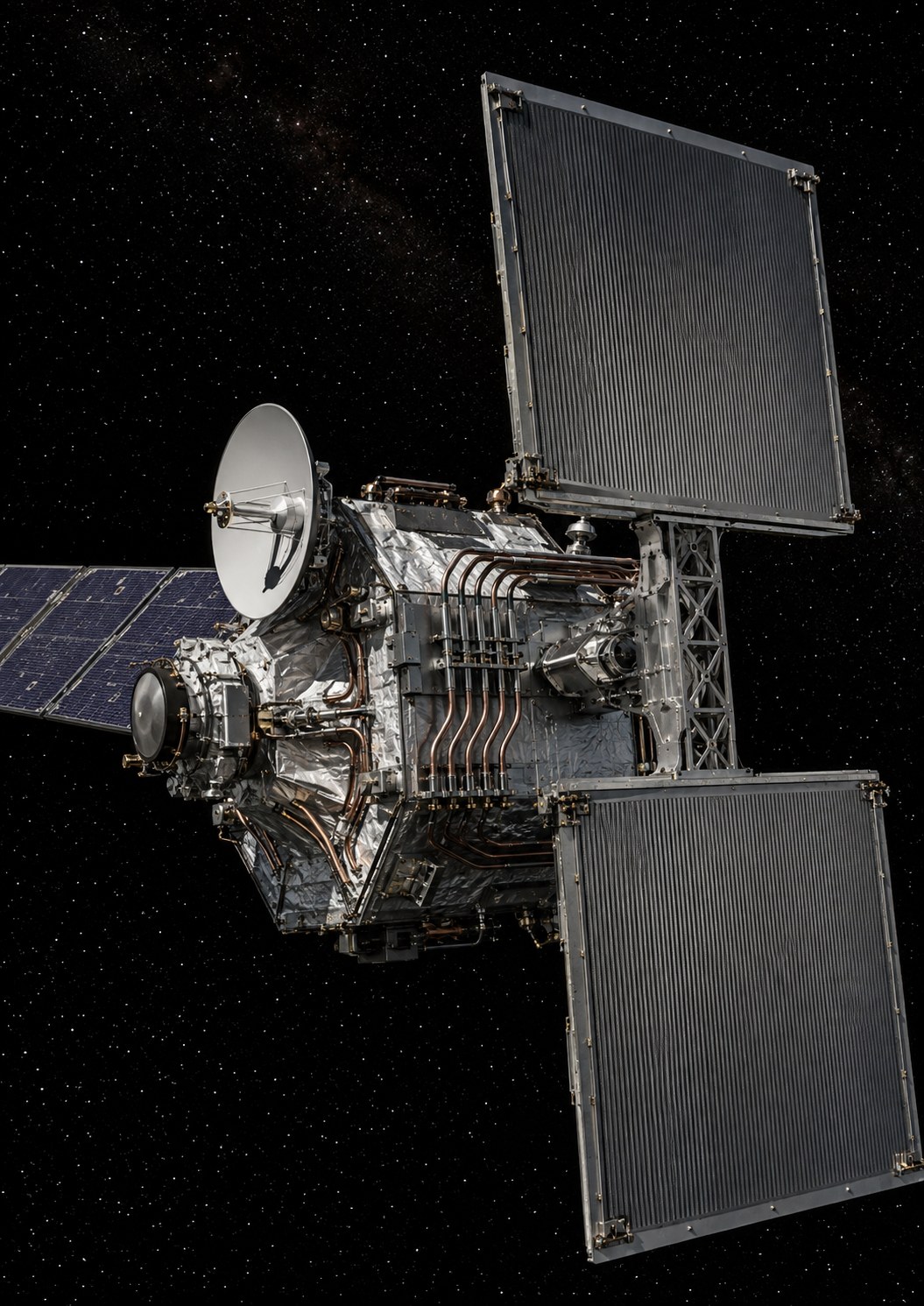
Why thermal control shapes the spacecraft
1. Thermal control is survival before comfort
Electronics, batteries, seals, fluids, instruments and humans all have allowable temperature ranges. Too hot, a component ages, drifts or fails; too cold, a battery loses capability, lubricant behaviour changes or fluid freezes. Thermal control must therefore protect limits in every mode, including low-power states. A backup mode that saves electrical energy while letting a critical line freeze is not truly safe.
2. In vacuum, no external convection
On Earth, air carries heat away. In space vacuum, external exchange is mainly radiation. Internally, heat moves through conduction and sometimes fluid loops. Continuous waste heat must eventually be radiated. This is why radiator area and optical surface properties matter. 'Space is cold' does not mean a spacecraft cools automatically: a sun-facing surface can absorb substantial energy while another radiates to deep space.
3. Conduction: heat follows real interfaces
A hot box does not transfer heat into a panel merely because they touch on a drawing. Thermal resistance depends on material, contact area, fastening pressure and interface materials. Thermal straps or heat pipes create preferred paths, while insulation or limited contact can deliberately restrict flow. Mechanical interfaces are therefore thermal interfaces too.
A radiator needs sufficient area and a favourable field of view. If it sees the Sun, a planet or a warm spacecraft surface, it absorbs incoming radiation. Orientation and attitude therefore matter. Radiative heat rejection scales strongly with absolute temperature, approximately with the fourth power in the Stefan-Boltzmann relation. Higher radiator temperature increases rejection, but equipment limits constrain how far temperatures may rise.
5. MLI, coatings and sunshields: control what enters and leaves
Multilayer insulation reduces radiative exchange between surfaces. Coatings select solar absorptance and infrared emissivity. Sunshields change the environment seen by instruments. Those properties can change with contamination, ultraviolet exposure and ageing, so thermal materials are functional components whose quality, installation and lifetime must be controlled.
6. Heaters: spend energy to avoid freezing
Heaters protect batteries, water or propellant lines, mechanisms and electronics during cold phases. Their power belongs in the worst-cold-case electrical budget. Sensor failure can prevent heating or leave a heater stuck on, so critical strategies use limits, redundancy or hardware protection. Even a simple heater becomes an electrical, thermal and software system.
7. Heat pipes and fluid loops: transport heat
Heat pipes move heat through evaporation and condensation of an internal fluid without continuous mechanical pumping. Pumped loops offer more control but add pumps, valves, leak risk and power consumption. The choice depends on heat load, distance, orientation, temperature and maintainability. Crewed vehicles may need complex thermal networks linking cabins, electronics, life support and radiators.
8. Transient behaviour: how long before a limit is reached?
Hardware has thermal capacitance, so temperature takes time to change. This can allow short peaks without sizing a radiator for indefinite operation. Steady-state and transient analyses therefore answer different questions. A ten-minute manoeuvre may remain below a limit and cool later, while a small imbalance lasting days can become critical. Duration is part of the thermal problem.
9. Thermal-vacuum testing: make the model answer to reality
Models predict temperatures and heat flows; thermal-vacuum tests measure real response in a controlled environment. Engineers compare measurements with predictions and correlate the model where justified. Hot-cold cycling can also expose contact, cracking, delamination or drift problems. The goal is not merely to 'pass the chamber' but to obtain evidence that model, hardware and margins describe mission cases well enough.
10. Mars surface: the problem changes again
On Mars, a thin atmosphere exists, the ground exchanges heat, day-night cycling is strong and dust can cover surfaces. External radiators therefore do not see the same environment as in cruise. Water lines, tanks, airlocks and outdoor equipment cycle in temperature. A settlement will distribute and transport heat across buildings and machinery, making thermal control an urban infrastructure.
11. Thermal failures can cascade
A stopped pump can overheat a converter; software then sheds loads; reduced heater power cools a battery; the cold battery delivers less power. Thermal failures can therefore cascade across subsystems. Protection must be coordinated and crews must understand dependencies. Temperature sensors, alarms, trends and simple time-to-limit estimates become operational tools, not just engineering data.
Without pretending to size a real mission, a simple example shows the logic. If equipment dissipates 1,000 W and a surface can reject an average 250 W per square metre in the chosen case, ideal useful area is 1,000 ÷ 250 = 4 m². Real design then accounts for emissivity, temperature, Sun, view factors, contamination, margins and transients. Division answers a simple question: how many square metres are needed if each square metre rejects a given power?
Emissivity describes how effectively a surface emits thermal radiation; solar absorptivity describes how much sunlight it absorbs. Radiators often benefit from high thermal emission and low solar absorption, but the required balance depends on location and mode. Coatings and ageing change those properties. A surface that looks shiny to the eye is not automatically thermally good or bad because the relevant wavelengths differ from human vision.
14. Thermal time: using heat capacity
A material mass can absorb energy before its temperature rises substantially. Sensible heat is approximately Q = m × c × ΔT, where m is mass, c specific heat and ΔT temperature change. This explains why a water tank can buffer thermal transients. But thermal mass does not eliminate heat; over long duration, heat must still be rejected or dissipation reduced.
15. Cold spots, condensation and humidity in habitats
In a pressurised volume, a locally cold surface can condense humidity. That water can promote corrosion, biological contamination or electrical faults. Crewed thermal control therefore interacts with ventilation, humidity control and insulation. Average cabin temperature is not enough; hidden cold spots behind panels and equipment matter.
16. Frozen fluids turn thermal failure into mechanical failure
A water or propellant line that freezes can become blocked, deformed or damaged depending on fluid and geometry. Thermal strategy defines survival temperatures, heaters, sometimes minimum circulation and drain procedures. A sensor in the wrong location may miss the true cold point, making sensor placement part of architecture.
17. Mars dust and surface properties
Dust deposited on a surface can change absorption and emission, interfere with louvers or reduce solar production. Exact effects depend on surface and deposit, so universal invented percentages should be avoided. Architecture needs inspection, performance measurement, cleaning or justified margin. Dust couples thermal, power, mechanisms and surface operations.
18. Reuse heat instead of only rejecting it
In a settlement, some machines produce heat while other spaces need heating. Heat exchangers can transfer that energy before rejecting it. This is not free energy; available temperatures and losses limit usefulness. Integrated architecture can nevertheless reduce electrical heating and radiator needs, turning thermal management into energy policy.
In a crewed vehicle, a thermal failure does not always produce an immediate effect. After a pump, heater or fan stops, some temperatures drift gradually. Operationally useful information is then time to limit: minutes until a converter must be shut down, hours until a line approaches freezing, or time until the habitable volume leaves its acceptable range. Validated simplified models and measured trends support these estimates. They help crews prioritise actions rather than treating every alarm as equally urgent. Reference architecture therefore connects sensors with thresholds, drift rates, consequences and procedures. This is especially important on Mars where Earth support arrives too late to drive the response.
Outside a spacecraft, convection through air is essentially absent. Heat moves internally by conduction and is ultimately radiated to space. Radiator equilibrium therefore depends on rejected power, area, surface properties and what the surface sees: cold space, Sun, Earth, Mars or another warm vehicle surface.
Coatings, multilayer insulation, heat pipes, thermal straps, conductive interfaces, sunshields and radiators can manage heat with little continuous control power. Their performance still depends strongly on orientation, ageing, contamination, contact conductance and geometry.
Heaters protect batteries, fluid lines and mechanisms; pumps move coolant; cryocoolers reach very low temperatures. These devices consume power, depend on sensors and control logic, may vibrate and may fail. A survivable passive or degraded state is therefore valuable.
A heat-rejection surface can absorb heat if it sees the Sun or a warm planet. View factors and spacecraft attitude therefore matter. A communications pointing change can alter radiator illumination, coupling GNC, communications and thermal design.
Temperature has inertia. Steady-state analysis asks where temperature eventually settles; transient analysis asks how long it takes to reach a limit. For short manoeuvres or eclipses, time-to-limit can be more useful than final equilibrium.
Thermal models contain conductances, dissipation, radiative properties and geometry. Thermal-vacuum tests measure actual temperatures and response so the model can be correlated. Hot-cold cycling can also expose workmanship and material problems.
Mars surface thermal control is not deep-space thermal control. Thin atmosphere, soil coupling, daily and seasonal temperature cycles and dust modify the environment. Habitats, external equipment, fluid lines and power systems form a distributed thermal infrastructure that must be maintained.
In vacuum, a crewed spacecraft absorbs solar energy, generates heat in equipment and people, temporarily stores part of that energy in its mass and ultimately rejects most of it by radiation. In a near-steady state, energy entering must leave. If a habitat consumes 12 kW of electrical power and only a small fraction leaves as stored or transported energy, nearly all of those 12 kW eventually becomes heat that the thermal system must handle.
The balance must be closed by operating mode: nominal cruise, maneuver, high activity, safe haven, pump failure and unfavourable attitude. The worst hot case is not necessarily the worst cold case. A radiator sized for active equipment can overcool a loop in survival mode. Valves, heaters and variable conductance exist to adapt the architecture across those regimes.
Thermal design is therefore a network of sources, resistances, capacities and sinks. A local temperature means little without the path by which heat enters and leaves. Models and tests must represent real interfaces, including contacts, insulation, cables, lines and supports.
Ideal radiation can be estimated from P = εσA(T⁴ − Tbackground⁴), where P is rejected power, ε emissivity, σ the Stefan-Boltzmann constant, A area and T absolute temperature. Neglecting the deep-space background for a teaching example, a 300 K surface with ε = 0.9 radiates roughly 413 W/m². Rejecting 10 kW therefore needs an ideal area of about 10,000 ÷ 413 ≈ 24.2 m².
This is a theoretical lower bound, not a design number. The radiator may see the Sun, a planet or warm spacecraft surfaces; fluid temperature is not uniform; performance degrades and margin is required. Lower rejection temperature sharply reduces watts per square metre because of the T⁴ term. Equipment temperature requirements therefore directly influence thermal-system mass.
Placement becomes an architecture problem. A large radiator must avoid thruster plumes, retain a cold field of view, avoid obstructing antennas and survive deployment mechanisms. Its physics may be simple while its geometry is difficult.
A thermal system has inertia. When a pump stops, temperature does not instantly jump to the limit; fluid, hardware and structure absorb energy. A simple approximation is Q = m c ΔT, where Q is stored energy, m mass, c specific heat and ΔT temperature change. If an equivalent thermal capacity is 5 MJ/K, an unremoved 10 kW load would raise its average by about 1 K in 500 seconds, a little over eight minutes, if other heat paths are neglected.
This shows why “time to limit” is often the useful operational quantity. A battery, avionics box and crew cabin have different inertia and temperature limits. FDIR can prioritize the fastest-moving hazard and shed heat-generating loads before damage becomes irreversible.
Transient models also govern recovery. Equipment cooled too far can condense moisture, fluid can freeze and seals can change behaviour. Returning to nominal may require controlled warm-up, purging or thermal equalization rather than a simple restart.
Pump, heat exchanger, line, valve, accumulator, sensor and radiator form one function. A leak reduces inventory; gas ingestion can damage pump performance; a stuck valve redistributes flow; a bad sensor can drive control in the wrong direction. Functional redundancy must therefore preserve the chain, not merely duplicate one pump.
Two-loop architectures can separate a crew-compatible internal fluid from an exterior fluid chosen for harsh temperatures. The heat exchanger adds hardware but limits some leak consequences. Fluid selection depends on temperature range, viscosity, toxicity, material compatibility and freeze risk.
Maintenance needs isolation points, refill capability, purging and component replacement. A high-performance loop that cannot be serviced after ten years is not durable. Service interfaces, spare-fluid volume and cleaning procedures belong in the original design.
Surface systems no longer see only deep space. Ground, thin atmosphere, sunlight, deposited dust and day-night cycles change heat exchange. Dust can alter solar absorptivity and infrared emissivity, pushing real performance away from the clean-surface model. Inspection, cleaning and in-situ measurement become part of thermal operations.
Heat recovery becomes attractive at base scale. Waste heat from electronics, electrolysis, computing or industry can preheat water, air or greenhouse loops. Reuse is only effective when temperature levels match; low-grade heat can contain substantial energy while being poorly suited to high-temperature processes.
At one thousand residents, thermal control becomes an urban network of industrial sources, habitats, storage, radiators and backup loops. Integration can save energy but also create common-cause failures. Building interfaces should enable useful heat sharing without making the whole settlement dependent on one loop.
In vacuum, a radiator rejects energy primarily by radiation. A useful approximation is q = εσT⁴, where q is heat flux in watts per square metre, ε is surface emissivity, σ is the Stefan-Boltzmann constant and T is absolute temperature in kelvins. For ε = 0.9 and T = 300 K, ideal flux is about 413 W/m². Rejecting 10 kW would therefore require roughly 10,000 ÷ 413 ≈ 24.2 m² before corrections for Sun or planet view, degradation, fluid temperature and margin. The equation immediately shows why thermal control is also a geometry problem.
Raising radiator temperature reduces required area because of the T⁴ term, but hardware and fluids may not tolerate that temperature. Sizing is therefore a trade among area, mass, pumping, materials and allowable equipment temperature.
A system that can reject 20 kW at steady state may still fail during a transient if heat arrives faster than it can be transported. Thermal mass can temporarily store energy according to Q = mcΔT, where Q is energy, m is mass, c is specific heat and ΔT is temperature change. That storage buys time but does not eliminate the later need to reject the heat.
Critical phases such as propulsion, attitude change, pump loss or environmental transitions need time-domain analysis. Operators need to know how many minutes remain before a battery, power converter or habitat crosses a limit and which loads can be reduced to buy additional time.
Useful thermal redundancy has to survive common causes. Two identical pumps on one bus, controlled by one software chain and connected to one radiator do not create four independent barriers. Loops, isolation valves, sensors, supplies and heat-rejection surfaces have to be analyzed as alternate paths after failure.
At settlement scale, waste heat also becomes a resource. Workshops, greenhouses, data systems and reactors can exchange heat before final rejection. That does not create free energy, but it can support preheating, freeze protection, drying and industrial processes while reducing otherwise wasted thermal flows.
Thermal balance has to be recomputed for actual mission modes: nominal cruise, sleep, high-power communications, trajectory correction, one-loop failure, Mars approach and survival after partial power loss. In each mode, internal and external heat inputs must remain compatible with transport and rejection capacity. Margin quoted for nominal cruise is meaningless if survival mode reduces pumping or changes attitude so that radiators see a worse environment.
This mode matrix also improves load-shedding decisions. Turning equipment off saves electricity but may remove useful internal heat; reducing a computing load may relieve both electrical and thermal systems. The two budgets are coupled, which is exactly the kind of cross-system dependency a technical reference should make explicit.
Heat does not simply disappear in vacuum. External convection is essentially absent, so energy must conduct through interfaces, move through structures, heat pipes or fluid loops, and finally leave through radiation. This chain explains why a thermal failure can propagate even when no electrical component has initially failed. A computer keeps running while its sink warms; a pump stops and flow collapses; a radiator remains cold while an avionics rack crosses its temperature limit.
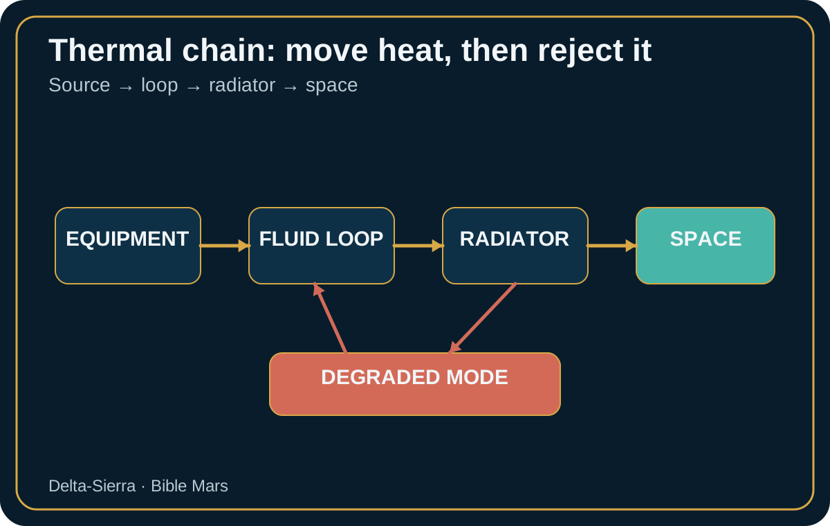
A Mars transit includes very different thermal regimes. Crew volumes need a narrow comfort range, batteries and electronics have their own limits, tanks and lines may require heaters, and external surfaces alternately see the Sun and deep space. Coatings, multilayer insulation, radiator placement and attitude therefore belong to the same architecture. A radiator is effective when it sees a cold environment but can absorb unwanted energy when badly exposed to the Sun.
For an ideal radiator, emitted power is approximately P = ε σ A T⁴, where P is watts, ε is dimensionless emissivity, σ is the Stefan-Boltzmann constant, A is area in square metres and T is absolute temperature in kelvins. If 6 kW must be rejected at 300 K with ε = 0.85, ideal radiative capability is about 390 W/m². The corresponding area is roughly 6,000 ÷ 390 ≈ 15.4 m² before view factors, absorbed sunlight, degradation and margin. ε is the Greek letter epsilon and represents emissivity here.
The calculation exposes an architectural coupling: most extra electrical consumption eventually becomes heat. A 100-kW spacecraft is not only a generator and cabling problem; it may require very large radiator area depending on operating temperature. Power level, loop temperature and external geometry cannot be optimized independently.
A steady-state model asks whether the system can remain indefinitely at a nominal condition. An emergency asks how long remains before a limit is crossed. Thermal mass provides useful inertia. If 500 kg of equipment has an average specific heat of 900 J/(kg·K), its bulk heat capacity is about 450,000 J/K. A 2-kW unremoved heat load would ideally raise its average temperature at about 2,000 ÷ 450,000 ≈ 0.0044 K/s, or about 16 K per hour. Real gradients and heat paths make the result much more complex, but the order of magnitude shows why a failed pump may leave tens of minutes or hours rather than seconds.
“Time to limit” should therefore be an operational quantity. It helps crews decide whether to restart a loop, shed loads, isolate a branch or change attitude. It also prevents misleading alarms: one hot sensor does not necessarily mean the whole structure is close to failure. Sensor location and thermal time constants matter.
Perfect redundancy is rarely practical. A degraded mode may tolerate hotter electronics, shut down experiments, reduce flow, concentrate the crew in one zone and preserve only essential vehicle control. That requires valves, bypass paths, sensors and procedures designed in advance. Serviceable interfaces and access to pumps or heat exchangers can determine whether an anomaly is recoverable.
Thermal models depend on contact conductance, surface properties, dissipation and configurations that carry uncertainty. Thermal-vacuum testing compares those assumptions with hardware. NASA's 2026 thermal-control state-of-the-art review distinguishes passive and active technologies including coatings, MLI, thermal straps, heat pipes, louvers, deployable radiators, phase-change materials, heaters and cryocoolers.
A Mars spacecraft should therefore be treated as a map of heat flows. Every major heat source needs a nominal rejection path and a survival path after failure. The same map guides maintenance: anomalous temperatures can be traced physically from load to radiator rather than treated as isolated numbers.
NASA Thermal Control, May 2026; JSC Thermal Management Subsystems; and NASA Spacecraft Components.
A useful thermal analysis traces where heat is produced, which interfaces it crosses, how structure or fluid transports it, which radiator rejects it and which valves can reroute it. Electrically separate computers can share one thermal common cause. A single pump in a common loop can turn two redundant computers into false redundancy.
Thermal capacitance provides a different kind of margin. If a 200 kg assembly has an average heat capacity of 900 J/(kg·K), allowing a 10 K rise stores about 200 × 900 × 10 = 1.8 MJ, or 0.5 kWh. With 2 kW of excess heat, that inertia offers only 0.5 ÷ 2 = 0.25 h—fifteen minutes—before the simplified limit is reached. A large metal mass is not automatically an hours-long thermal safe haven.
Failures need classification by dynamics. Loss of one radiator may evolve slowly; a stopped fan in a dense electronics rack can form a hot spot within minutes; a freezing pipe may take hours yet be hard to reverse. Alarms should therefore monitor trends and rates of change, not only absolute thresholds.
Condensation links comfort, environment and reliability. A surface below dew point can accumulate water near insulation, connectors or sensitive materials. Humidity control is therefore coupled to wall temperature and ventilation. Dew-point analysis belongs in failure modes of airflow and hidden cavities.
External layout matters as well. Radiators should not sit where plume contamination, dust or moving structures degrade their view. Deployment mechanisms introduce their own failures. A compact fixed radiator can be more robust than a nominally superior but mechanically complex surface.
On long missions, performance should be recalibrated. Comparing estimated dissipation, measured temperature and pump state can reveal gradual degradation. Small persistent differences may indicate fouling, gas in a loop, sensor drift or coating change. Thermal control becomes a diagnostic discipline, not only a prelaunch simulation.
External surfaces are selected through absorptivity and emissivity, two properties that should not be confused. Solar absorptivity determines how strongly a surface absorbs incoming sunlight; infrared emissivity affects how effectively it radiates heat. A useful radiator often seeks low solar absorption and high infrared emission, but coatings age. Ultraviolet exposure, contamination and deposition can shift properties over a multi-year mission. Thermal margin therefore includes material aging, not only clean-room performance.
Multi-layer insulation reduces radiative exchange but is not a magic blanket. Compression, gaps, penetrations and conductive fasteners create paths around it. MLI also changes the behavior of equipment during a failure: an object well insulated from the environment can retain unwanted internal heat. Thermal design must follow actual interfaces rather than assuming one generic insulation factor.
Freezing of working fluid is a particularly dangerous transition because a thermal problem can become mechanical. Ice or frozen coolant changes volume, blocks passages and can overload lines or seals. Heaters on vulnerable regions, circulation strategies, low-temperature fluid selection and minimum survival power all protect against this. The safe state for a power failure must therefore include the thermal loop.
Dust and contamination matter even before the spacecraft reaches the surface. Thruster products, outgassing and material deposits can alter radiator optical properties. Once on Mars, fine dust can cover external surfaces, mechanisms and heat exchangers. A radiator that loses performance slowly may consume power margin for months before an alarm threshold is crossed. Trending is essential.
Heat recovery can be as valuable as heat rejection. Warm equipment, processing systems or waste streams may support water heating, cabin conditioning or another process. The usefulness depends on temperature level: low-grade heat cannot replace a high-temperature industrial furnace, but it can reduce electrical heater demand. Integrated thermal design therefore asks where heat should go before asking how to throw it away.
Thermal qualification must include uncertainty. Model parameters such as contact conductance, emissivity and internal dissipation are never perfectly known. Thermal-vacuum tests tune the model, but a long Mars mission will encounter configurations that were not reproduced exactly on Earth. Instrumentation and recalibration keep the model useful after launch.
A thermal loop has two pumps but one common heat exchanger feeding a radiator. The active pump stops. Flow falls while equipment continues generating heat. The first minute confirms that the indication is real: motor current, pressure and temperature differences distinguish lost circulation from a bad flow sensor. The backup pump starts but delivers less than nominal flow.
If the zone dissipates 8 kW and degraded transport can remove only 5 kW, excess heat is 3 kW. Suppose effective thermal mass can absorb 1.5 kWh before a limit; the simplified time is 1.5 ÷ 3 = 0.5 hour. The crew has thirty minutes unless at least 3 kW of heat generation is removed or rejection improves.
Not every electrical shutdown helps. Turning off a science computer directly removes heat; stopping another circulation device may make the thermal condition worse. Thermal shedding therefore needs its own consequence table rather than copying electrical priority.
Attitude can buy another margin by improving radiator view, but may reduce solar power. A temporary loss of generation may be acceptable if thermal rejection improves enough. Disciplines negotiate through pre-established limits.
After stabilization, the team searches for motor, power, bearing, cavitation, sensor or blockage causes. Return to nominal is not automatic after one successful restart; an intermittent pump can be more dangerous than a deliberate degraded mode. Good thermal architecture buys time, explains state and preserves multiple recovery paths.
A crewed spacecraft can use occupancy itself as a thermal-management variable. Moving crew away from one compartment reduces metabolic and equipment heat there while increasing load elsewhere. During an emergency, a safe haven therefore needs not only pressure and atmosphere but enough cooling capacity for concentrated people and electronics.
Heat transport paths should be mapped against compartment boundaries. Closing a hatch or isolating a module may remove airflow or a fluid connection that the nominal thermal model assumed. A thermal-safe configuration must be compatible with fire and depressurization configurations rather than defined independently.
Cold survival deserves equal attention. Loss of main power can allow external lines, valves or batteries to fall below allowable temperature even when the cabin remains comfortable. Survival heaters need their own emergency energy allocation. The minimum electrical mode and minimum thermal mode are two views of the same vehicle state.
Thermal sensors also require redundancy in placement, not merely quantity. Three sensors mounted on the same warm plate may all miss a hidden cold spot or blocked airflow region. Instrumentation should observe both equipment and transport path: source temperature, coolant inlet/outlet, wall or radiator conditions and flow.
Maintenance operations change thermal conditions. Removing a panel can eliminate a conductive path or airflow guide; replacing a pump can introduce gas into a loop. Procedures should state temporary temperature limits and required purge or rebalancing steps. Repair is part of the thermal model.
The long-term objective is graceful degradation. A spacecraft should be able to identify how many kilowatts of heat it can reject in each degraded configuration and automatically connect that value to allowable electrical loads. Thermal state then becomes an explicit operational resource.
Thermal design also needs explicit sensor-failure logic. A single implausibly cold reading can cause unnecessary heater use, while a falsely low hot-zone reading can hide a dangerous condition. Cross-checking neighboring sensors, heat load and loop temperatures helps distinguish hardware change from instrumentation failure.
Crew activities create temporary thermal peaks. Exercise, cooking, maintenance with panels open, medical equipment and charging portable devices can all change local heat release. The operations plan should know which combinations are allowed during degraded cooling rather than discover the interaction during an emergency.
Finally, thermal margin should be expressed as time as well as temperature. 'Five degrees below limit' means little without knowing the current rate of rise. Displays and procedures that estimate minutes to threshold help crew act before a slowly developing failure becomes irreversible.
Radiator segmentation can reduce common-cause loss. Separate panels and flow paths allow one damaged surface to be isolated while preserving rejection elsewhere. Segmentation costs plumbing and valves, but it converts some catastrophic failures into capacity reductions.
The location of thermal storage matters. Phase-change material or deliberate thermal mass near one load can buffer short peaks without enlarging the whole loop. Such storage is useful for transient equipment, but it must later be re-cooled; it shifts heat in time rather than eliminating it.
Cabin comfort limits should be distinguished from equipment survival limits. During an emergency, crew may tolerate a wider temperature range for hours if it protects batteries or avionics. Procedures can exploit these different limits without allowing condensation, dehydration or medical risk.
Surface operations introduce an additional cycle: dust cleaning, shadowing, cold soak and seasonal environment. A vehicle designed for transit and then reused near Mars needs thermal modes for both phases, not a cruise system plus ad-hoc heaters.
Thermal control also influences emergency shelter duration. A safe haven may have enough oxygen and water for many hours but insufficient heat-rejection area for concentrated crew and electronics. Survival calculations should therefore include maximum sustainable internal heat load in the refuge configuration, with realistic pump and radiator availability.
Heat-leak paths can be intentionally designed. A passive conductive strap may carry only modest power in nominal operations but provide a no-pump route that prevents one component from freezing or overheating after active-loop loss. Passive paths add mass yet can provide valuable graceful degradation.
Testing should include transitions between heater and cooling modes because control logic can oscillate when sensor lag is large. Cycling wastes power and increases thermal fatigue. Tuning a controller is therefore part of hardware life management, not merely comfort control.
In vacuum, P = εσA(T⁴−T_env⁴). With ε = 0.85, σ = 5.67×10⁻⁸ W/m²/K⁴, A = 20 m² and T = 300 K, the deep-space term is small and P is about 7.8 kW. ε is emissivity, A area and T absolute temperature.
A stopped pump or mispositioned valve can create a hot spot while the radiator remains cold. Electrical load shedding must be coordinated with thermal inertia so the fault is not merely moved elsewhere.
Thermal-vacuum tests, correlated models and loop faults must demonstrate maximum temperature, gradient, time to limit and restart after cooling.
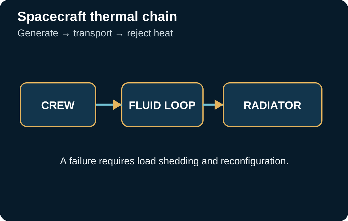
Vacuum removes external convection: heat from crew, electronics, converters, and equipment must be conducted to radiators and then radiated. Thermal control is therefore an energy-transport chain, not a simple thermostat.
Internal load changes with operations. High-power communications, a trajectory correction, or simultaneous science equipment can move several kilowatts of heat through the vehicle. Loops must survive these transients without exceeding sensitive-component limits.
The external environment also varies: solar distance, orientation, spacecraft shadowing, and views to warm surfaces change radiative fluxes. Hot and cold cases are both required, and the worst case does not necessarily occur at the same mission phase.
A radiator must retain a clear radiative view. A surface shadowed by structure, heated by a plume, or degraded by contamination can lose capacity without any conventional mechanical failure.
Equipment can be connected through liquid loops, heat pipes, or structural conductance depending on power and temperature range. The choice sets mass for pumps, plumbing, heat exchangers, and freeze protection.
One highly efficient loop creates a common cause. Two physically separate loops cost more but can preserve a vital subset after a leak or pump loss.
Equipment that tolerates a wide temperature range reduces control complexity. Batteries, medicines, selected sensors, and biological systems impose tighter windows that can become sizing drivers.
Thermal storage can absorb a short peak but does not replace adequate average rejection. A mass that stores 20 kWh eventually has to send those same 20 kWh to the radiator.
Radiated power depends strongly on absolute surface temperature. Raising radiator temperature can reduce area, but not all equipment and fluids can operate hot.
Nuclear systems and high-power propulsion make the trade even more visible: heat rejection can become a large structure. Research on lightweight radiators around 500–600 K illustrates that radiator mass and rejection temperature are first-order variables.
Available radiator area must coexist with antennas, solar arrays, sensors, propulsion, and docking operations. The whole spacecraft participates in the thermal problem.
A crewed architecture must provide access to valves, filters, and pumps. An external radiator may be impossible to repair in transit; internal reconfiguration must therefore limit the effect of its loss.
If 30 kW of electrical power enters a set of equipment and only 6 kW leaves as exported useful energy, almost all the remainder becomes heat that must be managed. The balance must state where that heat is deposited.
For a 25 kW heat load with two loops each able to reject 18 kW, the system survives loss of one loop only if degraded operation reduces load below 18 kW. Redundancy is therefore not binary; it depends on possible shedding.
A temperature limit must be paired with thermal inertia. A component that can operate ten minutes after cooling loss gives very different diagnostic time from one that exceeds its limit in thirty seconds.
A slow leak in the primary loop reduces pressure without immediate shutdown. The response must distinguish leakage from sensor error, isolate the segment, and redistribute loads before coolant is exhausted.
A pump stops during high electrical activity. Temperatures rise while the bus remains powered; thermal protection must shed load before electronics independently enter protection modes.
A radiator loses part of its sky view after spacecraft reconfiguration. No component has failed, yet thermal margin has changed. Flight configuration must therefore be part of the operational thermal model.
Finally, a biased temperature sensor can cause unnecessary cooling or hide overheating. Dissimilar sensors and simple energy balances provide a second diagnostic path.
Orion documents a real architecture combining radiators, heat exchangers, and active/passive thermal control; it is useful heritage, not direct Mars-transit sizing.
The completed project targeted lightweight radiator panels operating around 500–600 K for nuclear systems, illustrating the temperature-area-mass coupling.
Power, Habitation, and Transportation are separate but interdependent sub-architectures; thermal control sits directly at their interfaces.
In vacuum, a spacecraft cannot dump heat to its surroundings by convection. A fraction of electrical, metabolic, and propulsion energy must therefore be conducted to surfaces that radiate to space. This makes the radiator a structural design driver. TechPort work updated in 2026 on lightweight high-temperature radiators targets panels operating around 500 to 600 K with specific mass below 3 kg/m². Those values are technology goals, not a qualified Mars-vehicle design, but they show why a few tens of kelvins can strongly alter required area and mass.
The Stefan-Boltzmann law provides a first-order relationship: radiated power rises with the fourth power of absolute temperature. Raising radiator temperature can reduce area for a given heat load, but the cost appears elsewhere: pumps, fluids, seals, materials, electronics, and inhabited zones must tolerate the hotter loop or be isolated from it. The optimum temperature is therefore not simply the highest temperature available; it is a trade among area, mass, conversion efficiency, and life.
Thermal loads vary with flight mode. Electric propulsion may demand very high rejection during a long burn and then nearly disappear, while habitat and avionics remain continuous. The thermal network must span that range without freezing working fluids at low load or saturating radiators at high load. Freeze-tolerant and high-turndown radiator research illustrates why the ability to reduce heat rejection can be as important as peak rejection capacity.
In vacuum, a crewed spacecraft cannot dump heat into outside air. Energy must conduct from equipment into structure, fluid loops, straps, or heat pipes and eventually radiate to space. Every device is therefore a heat source and every interface a possible resistance. The balance must be written by mission mode. Computers at full load, food preparation, group exercise, battery charging, or a maneuver can move kilowatts from one compartment to another. A steady-state model predicts the final equilibrium after the system has settled; it does not tell the crew how many minutes remain after a pump stops or a valve sticks. Mars-transit thermal design needs two overlapping maps: equilibrium heat paths and thermal capacities that determine the pace of transients.
Radiator sizing exposes the direct relationship among power, temperature, and area. In a simplified model, radiated power is P = ε σ A (T⁴ − Tspace⁴), where ε is emissivity, σ is the Stefan-Boltzmann constant, A is area, and T is absolute temperature. Deep space is cold enough that the background term can often be neglected for a first estimate. A surface at 300 K with emissivity 0.85 radiates roughly 390 W/m²; rejecting 20 kW therefore calls for about 51 m² before geometry, degradation, view factors, and margin. Lowering the allowable radiator temperature increases required area sharply because of the fourth-power law. That simple equation explains why colder electronics are not free and why higher-temperature loops can reduce area while imposing tougher limits on fluids and hardware.
The Sun complicates heat rejection because a surface that emits efficiently can also absorb environmental radiation. Radiator placement must account for direct sunlight, reflections from the vehicle, and moving shadows. Solar-array orientation, engine plumes, shields, and other radiators can alter the radiative view. The Mars transfer also changes solar intensity, so hot cases near Earth and cold cases farther away may be controlled by different combinations of loads and attitudes. Designers need realistic hot and cold envelopes rather than one notional external temperature. Optical coatings age, surfaces can become contaminated, and micrometeoroids can damage exposed loops. A robust design knows how much degradation can occur before temperatures leave their qualified range.
Thermal capacitance buys time. If 500 kg of structure, fluid, and equipment has an average heat capacity of 700 J/kg/K, it stores about 500 × 700 = 350,000 J/K. With 5 kW of net heat no longer removed, the average temperature would rise at roughly 5,000 / 350,000 ≈ 0.014 K/s, close to 0.86 K/min in this very simple model. Ten kelvin of margin would then represent only about twelve minutes. Real spacecraft contain multiple thermal masses, exchanges, and possibly phase changes. The operational value of the estimate is that it translates a failed pump into time-to-limit. That time determines diagnosis priority, bypass needs, and how many decisions the crew can actually make before hardware damage becomes likely.
Thermal interfaces are easy to underestimate. Two bolted panels do not conduct like a single homogeneous block; contact pressure, roughness, interface materials, and aging alter the resistance. Harnesses can carry heat into supposedly cold zones. Fluid lines may warm nearby sensors or experience local cold spots in shadow. Thermal models therefore need correlation with integrated hardware measurements because contact resistance and parasitic paths are difficult to predict from geometry alone. Thermal-vacuum testing is not merely a pass/fail exposure. It calibrates the model that operations may later use to interpret an anomaly in flight.
An active loop includes pumps, valves, heat exchangers, accumulators, sensors, and control logic. Installing a second pump does not create meaningful redundancy if both depend on the same supply, an inlet that can lose prime, or one common valve. Failure analysis should begin with functions: move heat, retain working fluid, prevent freezing, control pressure, and protect heat-rejection surfaces. Engineers can then provide bypasses, isolatable sectors, and a reduced-flow operating mode. Degraded operation does not need to preserve nominal comfort; it must keep the crew and critical equipment inside a safe envelope long enough to repair or reconfigure.
A fluid leak is a defining scenario because it couples thermal control, cabin environment, and maintenance. A small leak may first look like pressure loss or gradual performance drift. The system needs a way to localize the section, isolate it, and estimate remaining inventory. If the fluid is hazardous or incompatible with cabin air, ventilation and protective procedures become part of the response. Make-up inventory should be based on plausible leak cases rather than an arbitrary percentage. Fluid choice also affects freezing risk, material compatibility, toxicity, pressure, and repair methods. A thermal choice therefore becomes a habitation architecture choice.
Heaters are the other side of thermal control. Low-power equipment can still require substantial energy simply to remain above its survival or startup limit. Lines, valves, and batteries may need temperature maintenance during low-activity modes. Heater loads belong in the electrical balance for cold cases, and heater failures must be detected before freezing or performance loss. Good zoning combines passive insulation with local heating so the entire spacecraft is not warmed to protect one component. Control logic must also distinguish a failed sensor from a real temperature drop; otherwise it may create an unnecessary or even hazardous heating response.
Human thermal loads add another constraint. The crew continuously produces heat and water vapor, while exercise, cooking, hygiene, and medical equipment create local peaks. A comfortable average cabin temperature does not prove that condensation, stratification, or hot spots are absent. Sensors should follow real airflow and heat paths rather than simply convenient wiring routes. Ventilation and thermal models need to be coupled: a capable heat exchanger is useless if warm moist air never reaches it.
Thermal anomalies should be rehearsed as timelines. A pump stops; flow falls; equipment continues dissipating; temperatures begin to diverge; the electrical system sheds selected loads; the crew isolates a branch; a backup path starts; the model estimates time remaining before the most sensitive component reaches its limit. Each step has an expected signal and a success criterion. Telling the event this way tests alarm quality and procedure feasibility. It also reveals design weaknesses: if the first observable symptom arrives after a component limit, the system cannot be diagnosed in time.
Maintenance must preserve hydraulic and radiative performance for months. A clogged filter, worn pump, fouled heat exchanger, or partly open valve erodes margin without causing an immediate shutdown. Trends in differential pressure, flow, pump power, and inlet/outlet temperature can expose the drift. Spares need supporting tools for draining, filling, leak checking, and return-to-service testing. Replacing a component is not the end of the job; the loop must be requalified enough for the crew to know that it can again carry the declared thermal load.
NASA's 2026 small-spacecraft thermal-control chapter is a useful map of coatings, multilayer insulation, thermal straps, interface materials, deployable radiators, heat pipes, phase-change materials, and active devices. Johnson human-spaceflight references add the operational context of inhabited systems. A small uncrewed spacecraft cannot be treated as direct proof for a Mars transport with metabolism, long-duration repair needs, and much larger internal loads. These sources instead provide mechanisms and technology families whose interfaces must be validated in the larger crewed architecture.
In interplanetary space, heat does not disappear. It must be moved from equipment and crew to a surface that can radiate it. Thermal control is therefore a complete chain: generation, internal conduction or convection, possible fluid loops, heat exchangers, transient storage and radiators. A weakness anywhere in that chain can limit the vehicle even when electrical power and propulsion remain available.
The sources of heat also change. Crew metabolic load is nearly continuous, avionics vary with operations, converters dissipate more during electrical peaks, and experiments or workshop loads may operate only for hours. Outside the vehicle, solar input changes with heliocentric distance and attitude simultaneously changes solar heating, radiator view and communications geometry. The design therefore needs hot and cold envelopes rather than one average temperature.
A first-order radiative relation is P = εσA(T⁴ − Tspace⁴). P is radiated power, ε surface emissivity, σ the Stefan-Boltzmann constant, A area and T absolute temperature in kelvins. For a surface near 300 K with ε = 0.85, ideal radiation toward a very cold background is on the order of 390 W/m². Rejecting 20 kW would therefore require roughly 20,000 ÷ 390 ≈ 51 m² in this simplified model. Real sizing changes with view factors, margins, degradation and allowable temperature.
This calculation shows why “cooler” is not free. At a lower temperature, each square metre radiates less and more area is required. At higher temperature, components, fluids and interfaces must tolerate it. Loop temperature is therefore a trade among radiator size, equipment efficiency, crew comfort, reliability and materials.
System mass can temporarily absorb heat. If an equivalent thermal mass of 500 kg has an average specific heat of 700 J/kg/K, thermal capacitance is C = m × c = 350,000 J/K. If a fault creates 5 kW of net unrejected heat, an ideal average temperature rise would be dT/dt = P/C = 5,000 ÷ 350,000 ≈ 0.014 K/s, about 0.86 K/min. Real temperatures are not uniform, so a local component may exceed its limit well before the average mass does.
Thermal inertia can still be an operational resource. During a brief maneuver, some heat may be stored and rejected later. Conversely, a pump loss in a low-volume loop can create a local hot spot within minutes. Failure modes need their time constants, not only labels such as nominal and backup.
Separating an internal transport loop from the external rejection loop can limit fault propagation and allow fluids suited to each environment. Heat exchangers, however, add mass, pressure drop, interfaces and leak paths. Two trains improve availability only when they do not share the same pump, power source, software function or vulnerable location. Duplication is valuable only when common causes are controlled.
Valve and sensor placement matters just as much. To isolate a leak, operators need to know which branch is losing inventory. Pressure, temperature, flow and sometimes mass balance provide that evidence. Too few sensors leave the crew blind; too many increase failures and calibration work. Useful instrumentation sits at boundaries where an isolation decision actually changes system state.
A thermal system may lose performance without a clear alarm: exchanger fouling, non-condensable gas, sensor drift, reduced pump head, wet insulation, contamination or a gradual change in radiator optical properties. These mechanisms require trend data. A value still “in range” but falling for thirty days may be more important than one mildly unusual instant.
Control logic must also avoid dangerous feedback. A temperature sensor drifts high, the controller raises pump speed, electrical demand increases, converter loss rises and creates more heat. An independent temperature measurement or an energy balance can expose the inconsistency. Thermal control is therefore a good candidate for cross-checks among temperature, electrical power and fluid flow.
Approach, maneuver, safe-haven operation or attitude loss can create the hardest thermal case. Arrays, antennas and radiators compete for orientation. A failed deployment can remove rejection area; a safe mode may choose a Sun-pointing attitude that is excellent for power but poor for radiator geometry. System architecture must search these combined constraints instead of optimizing subsystems independently.
NASA 2026 State-of-the-Art — Thermal Control describes current thermal technologies for small spacecraft, and its SmallSat scope should remain explicit. NASA — Orion spacecraft illustrates practical coupling among power, avionics, fluids and heat rejection on a crewed vehicle. These references illuminate principles and technology; they do not by themselves constitute a qualified crewed Mars transport architecture.
A cooling-loop pump shows a 15% decline in flow over several weeks. No alarm threshold is crossed, but inlet temperature at some heat exchangers slowly rises. The correct response is not automatically to replace the pump. Wear, filter blockage, a partly closed valve, a drifting flow sensor and a genuine change in thermal load must be separated.
Diagnosis combines several measurements. If pump electrical power stays stable while reported flow falls, obstruction or measurement error are plausible. If current rises as flow falls, friction or hydraulic difficulty becomes more likely. If temperatures remain consistent with the old flow, the flow sensor itself deserves suspicion. An independent thermal balance, Q̇ = ṁ cp ΔT, relates mass flow ṁ, heat capacity cp and temperature difference ΔT. It provides a second way to estimate transported heat.
Suppose the loop carries 8 kW with a fluid whose cp is about 4 kJ/kg/K and ΔT is 4 K. Expected mass flow is ṁ = 8 ÷ (4 × 4) = 0.5 kg/s. If the flowmeter reports 0.35 kg/s while heat load and ΔT remain consistent with about 0.5 kg/s, the instrument should be checked before an invasive repair. The calculation is useful only if the other measurements and fluid properties are trustworthy.
Opening a loop can lose fluid, introduce gas, contaminate the circuit or require a long purge. The design therefore needs local isolation, fill points, filtration and degassing provisions. Fluid and seal inventory becomes a mission resource. A pump described as “easy to replace” may be difficult in practice if the procedure empties the entire loop.
This case illustrates the difference between redundancy and maintainability. A second pump preserves immediate cooling, but it does not diagnose or restore the failed train. Long-duration survival requires both: continuity now and the ability to rebuild margin before the next redundancy is lost.
Thermal recovery should be prepared as a sequence rather than a simple switch to a backup component. After a loop loss, parts of the vehicle may have exceeded temperature limits, some fluid may contain gas or contamination, and electrical protection may have changed state. Return to service begins by establishing the real configuration: which branches are isolated, which volumes remain filled, which equipment experienced an excursion, and which measurements are still trustworthy.
A progressive strategy first establishes a small flow through a noncritical branch, confirms pressure, leakage and heat transport, then raises load in steps. Controlled ramp-up prevents an imperfect repair from immediately receiving full thermal power. It also lets operators compare measured response with expected behavior and detect a blocked exchanger, mispositioned valve or still-degraded pump.
Equipment that exceeded its temperature envelope needs separate disposition. A computer may reboot even though its remaining life has changed; a seal may have lost margin; a polymer may have embrittled. Continuing the mission therefore requires excursion history and reuse criteria, not merely the observation that “everything works again.”
Engineering models often focus on hardware limits, but crew comfort and health create narrower operational bands in occupied volumes. Local cold spots can condense moisture and support contamination; hot zones can increase fatigue and reduce sleep quality. Air mixing, humidity control and surface temperatures must therefore be considered together. A cabin average of 22 °C does not prove that a crew berth next to a cold wall or electronics bay is acceptable.
Humidity introduces latent heat. Removing water vapor by condensation transfers both moisture and heat into the thermal system. If crew activity raises metabolic and latent load at the same time that a radiator is constrained, the life-support and thermal budgets couple tightly. This is why a “crew day” profile is useful alongside hardware power profiles.
Radiator panels, pumps, valves, accumulators and heat exchangers must remain testable for years. A component hidden behind structure may save installation mass yet make a later leak impossible to localize. Test ports, isolation valves and replaceable pump packages add complexity but reduce the time spent with only one cooling path available.
Consumables also matter. Coolant makeup, filters, seals, lubricants and sensor calibration cannot be assumed infinite. A leak rate that appears tiny per day can matter over a multi-year mission. If 5 g/day of fluid is lost, one year consumes about 1.8 kg and three years about 5.5 kg before contingency margin. Long missions convert small rates into inventory problems.
After repair, the goal is not simply to bring temperatures back into range. The architecture should regain its redundancy, spare inventory and diagnostic confidence. If the backup pump remains installed permanently because the original cannot be repaired, the vehicle is living without its next layer of protection. Mission management must recognize that state explicitly and decide whether operations should be reduced until margin is rebuilt.
Feedback then closes the loop: update tests, modify trend thresholds, change spare inventory or improve an isolation boundary. Thermal safety on the way to Mars depends as much on this ability to learn as on initial radiator area.
Margins should not be stacked without understanding their origin. Uncertainty in internal heat load, radiator degradation and design contingency are not the same phenomenon. Blindly combining them can make a system unnecessarily heavy or, in the opposite direction, count the same reserve twice. A margin table should identify assumption, physical cause, data maturity and mission phase.
As testing improves knowledge, some margins can shrink while others emerge. Thermal design becomes a convergence process based on evidence: analysis, component test, loop test, integrated test and operational data. This hierarchy matters especially for a Mars vehicle that must function far from immediate terrestrial repair.
Average cabin temperature can hide local gradients near windows, equipment racks, ducts and crew quarters. A volume may satisfy a nominal setpoint while one sleeping location sees a cold radiant surface or one electronics bay recirculates warm air. Computational models and ground testing should therefore examine local flow and surface temperatures, not only bulk air.
Condensation is one of the consequences. A surface below the local dew point can collect water, alter insulation and create contamination concerns. Moisture removal in the life-support system does not guarantee that every surface remains dry. Thermal design and humidity control share this boundary.
Radiator performance depends on optical properties that can change with contamination, radiation and long exposure. A small degradation in emissivity or increase in solar absorptivity can shift heat-rejection margin. Long missions should therefore include degradation assumptions and, where practical, monitoring through temperature and energy balance.
Surface placement also matters for plume or vent contamination. Material released by thrusters, vents or maintenance operations should not deposit on critical radiator areas. Geometry and operating constraints can protect thermal surfaces without adding another subsystem.
After a repair, the goal is not merely to bring all temperatures back within limits. The spacecraft should recover its spare capacity, fluid inventory and confidence in sensing. If a backup pump remains permanently active because the original train cannot be repaired, the vehicle has lost the next layer of protection and mission operations should reflect that state.
That principle prevents a common reporting error: calling a system “nominal” because current temperatures are acceptable. Long-duration risk depends on what happens after the next failure. Restoring thermal margin is therefore part of the repair, not an optional later task.
Subsystem tests can demonstrate pumps, radiators and exchangers individually while missing the hardest integrated state. A spacecraft may simultaneously operate high-power communications, keep one radiator partly shadowed, run a degraded electrical converter and carry a crew exercise load. Integrated thermal verification should therefore reproduce combinations that are credible during flight, not simply maximum values tested one at a time.
Models need correlation against test data. If measured temperature response differs from prediction, changing a single tuning coefficient until the curve matches can hide the underlying reason. Flow distribution, contact conductance, sensor location and boundary conditions should be examined. A correlated model is useful only when the physical explanation remains credible.
Thermal control is often described as heat rejection, yet low loads can create freezing, viscosity or condensation problems. During safe mode, many electronics are off and internal heat falls. Lines and valves near external structure may require heaters. Heater demand then becomes part of the survival power budget, linking the cold case back to electrical storage.
Redundant heater control needs care. A failed-on heater can overheat an isolated component; a failed-off heater can freeze a line. Independent temperature limits and physically separated sensing may be appropriate for functions whose loss would be mission-critical.
Pump wear, radiator optical degradation, drifting sensors and reduced fluid inventory can combine after years. The return-to-Earth case may therefore have less margin than departure even if nominal mission geometry is easier. A system acceptable on day 1 should remain acceptable near day 900 with realistic degradation and repair history.
This is where maintenance planning meets thermal design. If a pump is expected to accumulate more cycles than demonstrated life, replacement should be designed into the mission. If radiator degradation is uncertain, extra area or higher-temperature operation may provide contingency. End-of-life is not a percentage on a spreadsheet; it is a physical configuration that should be analyzed.
The final verification step cross-links every thermal mode with other survival functions. Safe-haven operation, power loss or communications constraints can change both heat loads and available attitudes. Thermal models therefore belong inside system scenarios rather than in an isolated analysis. This integration can reveal that an electrically safe configuration is thermally poor, or that a cooling strategy consumes the very energy the safe haven is trying to preserve.
No thermal test can reproduce the entire trip to Mars. Gravity, vacuum, radiation environment, duration and every interface cannot all be simulated with equal fidelity at once. Verification therefore needs a chain of evidence: component tests for local properties, loop tests for hydraulic behavior, thermal-vacuum testing for interfaces, and correlated models for states that cannot be reproduced. Every level should state what it validates and what remains uncertain.
Correlation does not mean tuning a model until the desired curve appears. If a test warms faster than predicted, engineers should investigate contact resistance, flow, heat capacity or sensor representation. A physically justified correction can then propagate to other mission cases. An arbitrary factor may reproduce one test while failing exactly where the mission leaves the tested domain.
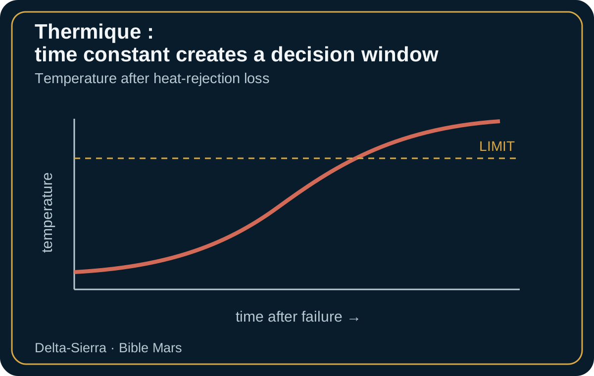
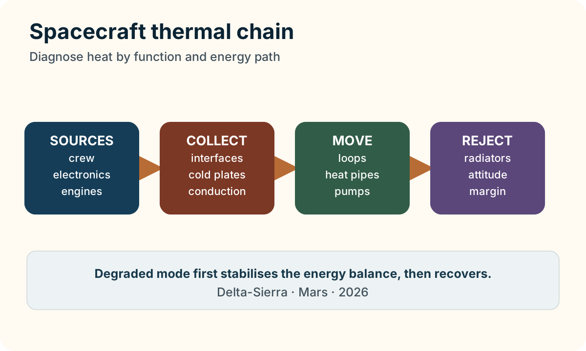
A crewed spacecraft thermal system is easier to reason about when it is treated as a chain rather than as a collection of heaters and radiators. Heat is generated by people and equipment, collected through conductive or convective paths, transported through structure, heat pipes or pumped fluid, and finally rejected by radiation. A break at any stage may present as rising temperature, yet the required response is different. This is why thermal fault isolation needs more than a temperature threshold.
A first radiative estimate is P = εσAT⁴. P is radiated power in watts, ε is dimensionless emissivity, σ = 5.670 × 10⁻⁸ W·m⁻²·K⁻⁴ is the Stefan–Boltzmann constant, A is area in square metres and T is absolute temperature in kelvins. With ε = 0.85, A = 20 m² and T = 300 K, an ideal surface facing cold space radiates roughly 7.8 kW. A real vehicle also sees the Sun, planets and its own geometry; coatings age and internal conductances limit what reaches the panel. The equation is therefore a transparent order-of-magnitude check, not a flight prediction by itself.
Real faults rarely arrive as a clean binary signal. Pump performance can drift downward, a valve can stick partway, a radiator can be poorly oriented during a manoeuvre, and a communications session may impose heat at the same time. Useful fault detection compares temperature trends with flow, pressure, commanded valve state and electrical dissipation. If all reasoning is tied to one high-temperature alarm, detection is late and isolation is ambiguous.
Degraded operation may shed noncritical electrical loads, shift activities in time, cross-connect loops, alter attitude when navigation permits, or confine habitation temporarily to a smaller thermal zone. Such responses buy diagnostic time. They also expose coupling: reducing electrical demand lowers waste heat, but turning off a pump or computer can remove a function needed to control the very anomaly being managed.
A single headline “20 percent thermal margin” can hide incompatible uncertainties. Margin against higher equipment dissipation does not automatically cover reduced coating emissivity, poorer conductance, lower coolant flow or partial radiator loss. A defensible margin ledger identifies each uncertainty, its unit, its assumed distribution or bound, and the verification evidence that will retire it. That discipline prevents a percentage inherited from one subsystem from being silently reused for another physical mechanism.
Stabilising safe mode is only half of a thermal failure story. The vehicle must also prove how cold equipment is rewarmed, how a loop is re-primed, how loads are restored in sequence and how sensors confirm that the original cause has not returned. Recovery transitions can produce the largest gradients because many dissipations change together. Test campaigns and simulations therefore need entry into degraded mode, dwell time, repair or reconfiguration, and controlled return to service.
For a Mars transit, the human interface should expose the energy path rather than present dozens of unrelated temperatures. Crew members need to know which zone is heating, which transport path is available, whether rejection capacity is constrained and what action consumes the remaining margin. This turns a complex thermal model into a manageable operational picture without pretending that the physics is simple.
Primary NASA sources
These references provide documentary guardrails;